NOAA Manual NOS NGS 1
Geodetic Bench Marks
U.S. DEPARTMENT OF COMMERCE
National Oceanic and Atmospheric Administration
National Ocean Survey, Rockville Md.
Lt. Richard P. Floyd
|

September 1978 |
|
Jump to TABLE
OF CONTENTS
Note: This file was generated by OCR scan from
a paper copy. As such:
- Obsolete information is unaltered to preserve the original 1978 text.
- Some additional inadvertent transcription error may exist.
- See the PDF version for a more authoritative source.
Jump to TABLE
OF CONTENTS
|
|
 |
|
|

|
NOAA Manual NOS NGS 1
Geodetic Bench Marks
Lt. Richard P. Floyd
NOAA Corps
National Geodetic Survey
Rockville, Md.
September 1978
U.S. DEPARTMENT OF COMMERCE
Juanita M.Kreps, Secretary
National Oceanic and Atmospheric Administration
Richard A. Frank, Administrator
National Ocean Survey
Allen L. Powell, Director
For sale by the Superintendent of Documents, U.S. Government Printing Office
Washington, D.C. 20402
Stock Number 003-017-00442-2
|
FOREWORD
Bench marks are long lasting points for which elevations have been determined,
used to control other surveys and to monitor movement of and within the
Earth's crust. They constitute the visual evidence of vertical control established
by the National Geodetic Survey (NGS), an office of the National Ocean Survey,
National Oceanic and Atmospheric Administration. Bench mark design and
setting procedures are important to the leveling program. In the past, however,
availability of materials and ease of setting were often the primary considerations
rather than soil mechanics, geology, properties of materials, and the like.
Advancing technology brought both the ability to determine elevations
more precisely and a greater need for bench marks to hold these elevations. The
releveling program for the new adjustment of the National Vertical Control Network
provided an ideal opportunity to upgrade the quality of NGS bench marks
to meet future geodetic requirements.
This manual was written for two main groups of users. One includes managers
and field personnel, both publicly and privately employed, who are involved
with setting bench marks that will meet NGS specifications. The guidance
given here must be adhered to strictly to obtain the quality required by the
National Geodetic Survey. The other group consists of the users of NGS vertical
control data. Supplementing other vertical control data, the information in this
manual makes it possible to judge the reliability of an NGS bench mark
elevation.
Because of a limited number of bench mark types, it is not possible to set
the optimal monument in every case. For some installations, geologists or other
specialists might be consulted. The manual includes enough detail to enable
judicious modification in design when the occasion arises.
Dimensions have been given only in metric units wherever feasible. Commercial
products are normally specified in English units, and consequently,
English units are given in parenthesis when applicable. A conversion table from
metric to English units is given in appendix A.
ii
CONTENTS
| Chapter |
Page |
| Foreword |
iii |
| Abstract |
1 |
| 1. Introduction |
1 |
2. Sources of vertical instability
|
2 |
|
Origins in the subsurface |
2 |
|
On or near-surface origins |
3 |
|
Motion intrinsic to the monument |
5 |
|
Intended stability of NGS bench marks |
5 |
3. Considerations in selecting a site
|
5 |
|
Security |
5 |
|
Utility |
6 |
|
Stability |
6 |
|
Corrosive environment |
10 |
|
Safety |
12 |
| 4. Installation |
12 |
|
Maintaining good public relations |
12 |
|
Special considerations at line intersections |
13 |
|
Disk set in bedrock or structure |
13 |
|
Class A rod mark |
14 |
|
Class B rod mark |
25 |
|
Miscellaneous marks |
26 |
| 5. Descriptions |
35 |
| Appendix A. Approximate conversion table: metric to English
units |
36 |
| Appendix B. The use of geopotential heights for Great Lakes
Vertical Datum |
37 |
| Appendix C. Soils |
41 |
| Appendix D. Existing monumentation in the vertical network |
43 |
| Appendix E. Examples for determining bench mark depths |
45 |
| Bibliography |
48 |
| Index |
49 |
|
TABLES
|
| 1. Summary of measures taken to set high-quality bench marks |
11 |
| 2. Sleeve depth for class A rod mark set within the
continental United States |
27 |
| 3. Minimum depth for class B rod mark |
27 |
|
FIGURES
|
| 1. Referencing of bench marks |
7 |
| 2. Intersection of lines-of-position |
8 |
| 3. NGS bench mark disk stamped with designation and year |
14 |
| 4. Sleeved class A rod mark |
16 |
| 5. Class A rod mark showing logo flange and hinged access
cover |
17 |
iii
|
| 6. Setting a sleeved class A rod mark |
20 |
| 7. Distribution of potentially expansive materials, Northeastern States |
28 |
| 8. Distribution of potentially expansive materials, Southeastern States |
29 |
| 9. Distribution of potentially expansive materials, North-Central States |
30 |
| 10. Distribution of potentially expansive materials, South-Central States |
31 |
| 11. Distribution of potentially expansive materials, Western States |
32 |
| 12. Climate factor |
33 |
| 13. Extreme depth of frost penetration |
34 |
| 14. Mississippi River flows uphill |
38 |
| 15. Elevation |
38 |
| 16. Geodetic reference ellipsoid |
39 |
| 17. The geoid |
39 |
Mention of a commercial company or product does not constitute an endorsement
by the NOAA National Ocean Survey. Use for publicity or advertising
purposes of information from this publication concerning proprietary products
or the tests of such products is not authorized.
iv
GEODETIC BENCH MARKS
Lt. Richard P. Floyd
National Geodetic Survey
National Ocean Survey, NOAA
Rockville, Md. 20852
| ABSTRACT.-Geodetic survey control points must be remarkably stable due to
the very intent of establishing geodetic control. All monuments are subject to
the effects of geologic and soil activity. Vertical control points are particularly
vulnerable because this activity results in vertical movements much more so
than horizontal motion. In addition to natural disturbances, damage inflicted
by mankind is a critical problem in monumentation. This manual explains how
and where to set bench marks for maximum stability and calls attention to the
factors that affect vertical instability. |
1. INTRODUCTION
To function as good references for elevations,
bench marks must be relatively stable points. Accordingly,
it is necessary to define what is meant
by stability before an understanding of high quality
monumentation can be gained. "Stability"
refers to the ability to maintain a fixed position.
It is characterized by its degree and duration.
To the local surveyor running a topographic
survey on a small construction site, a stable point
could be defined as the top of a prominent boulder
or a spike driven into a gravel road surface. These
objects are subject to movements of a few centimeters
to a decimeter or more in a year's time, but
they are adequate for the surveyor's needs. It
would be uneconomical to spend the time and
money necessary to set higher quality bench marks.
Another surveyor might be concerned with laying
out a major highway that could take years to
complete. Therefore, the control must be more
stable in its position and longer lasting. To this
surveyor, a stable point could be represented by a
concrete post extending to a depth of a meter or so,
or a spike in the side of a large utility pole. These
bench marks might hold their elevations within a
few centimeters while the project is being carried
out. It follows that the bench mark stability required
depends on the precision of the survey being
carried out and the duration of the project
for which the elevations are needed.
The National Geodetic Survey (NGS) of the National
Ocean Survey is responsible for establishing
and maintaining the National Networks of Geodetic
Control. The survey markers comprising
these networks serve as basic reference points for
numerous surveying, engineering, mapping, land
use planning, and scientific projects. If the networks
are to adequately serve these purposes, they
must be established to a high degree of accuracy
and monumented in a manner that best preserves
their original geodetic positions.
Stability requirements for the National Vertical
Network control points have increased significantly
in recent years due to continually advancing
technology. Both the ability to determine elevations
more precisely and the need to know elevations
more accurately have resulted from this
technological boom. Uses have increased from
basic control for boundary surveys and mapping
to large scale planning and construction of transportation
systems such as interstate highways and
transcontinental pipelines. More recently, increased
emphasis on crustal motion studies and
control for missiles, satellites, and spacecraft has
brought about a need for more accurately known
positions and, consequently, more stable control
points.
1
Elevations are referenced to a level surface, or
geoid, which is approximately equivalent to mean sea level.1 Not even the Earth's crust, which averages
35 kilometers in thickness, is stable relative to
the geoid. Young mountains are uplifting while
areas of the ocean floor subside. Ideally, a bench
mark used strictly for control should remain
motionless with respect to the geoid. Since the geoid
is intangible, the only basis we have for appraising
bench mark stability is the Earth's crust,
even though it is in constant motion. A monument
can be considered as stable as possible if it is motionless
with respect to the crust.
To clarify this, a distinction must be made between
crustal motion and motion within the crust.
Crustal motion is movement of the crust as a
whole. It is caused by phenomena such as isostasy
(the concept of the crust floating on the mantle)
and tectonic plate movement. Motion within the
crust originates above the base of the crust.
It is motion originating above the base of the
crust that we would usually like to prevent from
being transmitted to our bench marks. Prevention
being impossible, the next best thing is to reduce
the motion's effects. This can be done by (1) minimizing
surface effects and (2) with the aid of geological
information, avoiding or accounting for
movements of deeper origins.
The following chapters deal with identification
of the various factors that can cause changes in
bench mark elevations, and steps that must be
taken to set high-quality bench marks. These
marks include disks set in bedrock or structures,
sleeved rod type bench marks, rod marks with
disks, and some miscellaneous types.
2. SOURCES OF VERTICAL INSTABILITY
The subject of bench mark instability can be
more easily understood if it is separated into two
categories characterized by the depths at which
movement originates. Those with their roots within
about 15 meters of the surface will be called
"near-surface sources of instability," while those
that originate below about 15 meters will be called
"subsurface sources of instability." If the effects of
near-surface sources of instability cannot be avoided
by prudent selection of the bench mark
site, they can be counteracted so that they are not
reflected in the bench mark elevation. Subsurface
effects usually cannot be economically counteracted
by a suitable bench mark design so they must
be avoided or accounted for.
Bench mark movement can be likened to that of
a float bobbing up and down on the surface of the
ocean. The total vertical movement of the float is
the result of accumulated movements caused by
sea (locally generated choppy waves), swell (long,
rolling waves from a distant origin), and tide. At
times, these individual effects act together, amplifying
the total movement. For example, the
float might be lifted by a sea which is on the crest
of a swell at high tide. Other times, one effect will
tend to cancel another, as when the float is on the
crest of a wave which is in the trough of a swell.
At any rate, the float is in motion with respect to al
reference surface, which in this case is the ocean
floor.
To correlate this to bench mark movements, the
respective counterparts of sea, swell, tide, and the
ocean floor are near-surface movements, movements
within the crust, motion of the entire crust,
and the geoid.2 It would be ideal if we could fix the
bench mark to the geoid as we can anchor a piling
to the ocean floor to eliminate tidal motion. However,
there is no analogous way to counteract the
effect of crustal motion on a bench mark.
In the ocean, the effect of swell could be avoided
in some areas by making use of an existing breakwater,
harbor, or bay. Similarly, with proper
bench mark site selection, many movements within
the crust can be avoided, but choice of a location
is not as obvious. Considerable geological information
is needed to determine which areas exhibit no
subsurface instability.
Finally, the effects of sea in many situations can
be avoided. Where this is not possible, they can be
economically counteracted by building a small
floating barrier. Essentially, this is what can be
done for vertical control points. The sleeved class
A rod mark (see fig. 4, page 16) consists of a steel
rod that is isolated from near-surface motion by
the sleeve.
Origins in the Subsurface
Crustal Motion
First among the subsurface causes of vertical
movement is crustal motion. Even if it were possible
to prevent this movement, it would be undesirable
in many cases. Crustal motion studies are
an important application of leveling data. The
movement of one area of the crust in relation to
another serves as the basis for these studies. To
determine this, knowledge of crustal motion with
respect to the geoid is not essential. What is necessary
is to know which bench marks reflect only
crustal motion. Referring to the parallel drawn
with the sea surface, if a float is to be used to monitor
tides, it must be known that the effects of seas
and swell have been eliminated.
1 A concise, easily understood description of the geoid is given in appendix B.
2 The gravitational effects of the sun and moon exert an
influence on land masses just as they do on the oceans, causing a phenomenon known as "Earth tides." No analogy
for Earth tides is made in this parallel.
|
2
Caverns and Mines
Caverns and underground excavations contribute
to vertical movements on the surface of the
Earth. Sometimes the motion is abrupt as is the
case with sink holes, and other times their effects
result only in gradual subsidence. When crustal uplift
is occurring simultaneously with subsidence
caused by a gradual caving in of an underground
mine, the wrong conclusion can be drawn about
the stability of an area. In general, the National
Geodetic Survey is not concerned with monitoring
subsidence caused by underground excavations
and caverns. Since it is too costly to anchor bench
marks below the depth of disturbance and isolate
monuments against such movement, these areas
must be avoided wherever possible.
Pumping
Subsidence is also caused by pumping of oil or
water. When fluid is removed from the ground,
the resulting decrease in pressure allows gravity
to pull down the overlying soils. Associated with
this is piping, or the removal of fines from a soil
stratum, which aggravates the situation. Again, in
carrying out its basic mission of developing and
maintaining a network of geodetic control, NGS is
not primarily concerned with monitoring this
type of motion. Except where subsidence is the subject
of special study, such as in the Houston, Tex.,
area and Santa Clara Valley, Calif., these areas too
should be avoided wherever possible.
On or Near-Surface Origins
Impact
The reliability of a bench mark elevation is
largely dependent upon its exposure to impact.
The results of impact can range from an infinitesimal
change in elevation as a result of being stepped
on to total destruction caused by earth-moving
equipment, which is perhaps the most common
cause of bench mark loss. NGS bench marks have
been designed to minimize the chances of vandalism,
tampering by souvenir hunters, and impact
which is relatively small in magnitude.
For class A rod marks, this is accomplished by
three precautionary measures: first, the datum
point is set slightly below ground level; second, a
protective pipe is placed around the datum point;
and third, the bench mark component which is
imprinted with the NGS logo, and might be considered
a worthy souvenir, is not an integral part
of the datum point.
By their inherent nature, other types of NGS
bench marks are not vulnerable to relatively
slight impact. Heavy impact, such as that caused
by construction equipment, cannot be counteracted
by economical design so it must be avoided
by judicious placement.
Frost Heave
Besides disturbances caused by human intervention,
there are a great many resulting from
natural phenomena. Of these, frost heave is one
of the most severe. The occurrence of frost action
depends on three factors: freezing temperatures;
available water; and certain soil characteristics,
most notably soil particle size. The absence of any
one of the essential conditions precludes the occurrence
of frost heave.
For example, it is the influx of additional water
into a soil's freezing zone after the freezing has
already begun that results in excessive frost heave.
The freezing of water initially present does not
cause a significant problem. When the water table
is near the surface, additional water is available to
be drawn up into the freezing zone causing the
frost heave problem. A water table within 2 meters
of the ground surface indicates a potential hazard
and it is normally further from the surface on hills
than in low-lying areas. Consequently, less severe
frost heave can be expected to be found on hills.
Even though water is available, significant frost
heave will not occur unless the soil can draw it up
and hold it in the freezing zone. Soils which are
capable of this are called "frost susceptible." The
main factor in determining frost susceptibility of
a soil is particle size distribution. Coarse-grained
soils contain spaces that are too large to draw up
and hold water. At the other extremity, many clays
are impervious to water. (Clays, however, are detrimental
for reasons other than frost heave as
explained in other sections of the manual.) The
soils most susceptible to frost action, and therefore
to be avoided where freezing occurs, are silts and
silty sands with soil particle sizes less than 0.02
millimeter (U.S. Army Corps of Engineers 1967).
Shrinking and Swelling of Soil and Rock
Another phenomenon that can cause bench
mark instability is shrinking and swelling of soil
due to changes in moisture content. The magnitude
of soil volume change depends upon two
factors. One is the character of the soil, including
particle size and distribution, degree of cementation,
and, most importantly, mineralogy (Patrick
and Snethen 1976). Fine-grained soils containing
certain clay minerals, particularly montmorillonite,3
are highly expansive.
3 Montmorillonite is a clay-mineral made up of layered,
plate-like particles separated by water. The addition of more
water causes the particles to separate even more until they
finally disperse.
|
3
The other factor governing the shrinking or
swelling of a soil is the measure of its variation in
moisture content. Seasonal climate variability
provides a good indication of the degree and depth to which volume change will occur.4 An expansive soil subject to either a consistently moist or dry climate year around will not exhibit a change in volume,
but if the climate is wet during one season and
dry during another, a volume change will occur. Figure 12 (page 33) separates the United States into areas of differing climate variability. The higher the value of the climate factor, the
more variable the moisture content of the soil.
This expansive character is not limited to soils.
Sedimentary rocks are those which were formed by the consolidation of sediments. If the parent materials were of an expansive nature, the rock itself will likely have this characteristic to a surprisingly high degree. Substantial pavement damage has occurred on some highways founded on sedimentary bedrock when the water content has been altered.
Soil Expansion and Contraction
The terms "expansion" and "contraction" indicate changes in volume resulting from a change in temperature rather than a change in moisture content.
Like other materials, soil expands when its temperature rises and contracts when its temperature
is lowered. It differs from most other materials in that the range of temperature variation is not constant throughout its depth. At the surface, the temperature variation is near that of the air.
At some depth, the temperature is nearly constant
throughout the year. In unfrozen soils, expansion and
contraction due to temperature change is negligible,
but in frozen soils they are factors to
consider. In permafrost, temperature change can
have a significant effect on a bench mark down to
a depth of about 10 meters (Bozozuk et al. 1962).
Slope Instability
Slope instability covers a wide range of movements ranging from rockslides and mudflows to the nearly imperceptible movement known as creep. Rockslides and mudflows are obvious and would probably result in the total destruction of a bench mark. Creep presents a greater problem to monumentation because it could result in only a slight change in the bench mark elevation which could lead to erroneous conclusions. Evidence of creep can sometimes be witnessed in leaning utility poles where the upper layer of soil slides in relation to that beneath it.
Gravity is the main force that produces creep, but gravity can be aided by a number of other factors, among which the presence of moisture is probably the most dominant. In some instances, a small amount of water can increase cohesion and retard the flow of soil downhill. More often, water
decreases friction between soil particles, allowing
them to flow more rapidly. When moisture is confined to the upper layers of a slope by an impermeable substratum, the likelihood for creep is quite
high.
Sometimes a slope can be stable until a cut is
taken from it which upsets the equilibrium and starts a slide. If the cut was taken from an area
providing substantial support to a slope, the slide will occur rapidly. When the slope is less steep or
provides more of its own support through cohesion
of the soil, a cut will have no effect or result only
in creep. Highways are notorious for producing
slides in some parts of the country.
Soil Consolidation
When a soil mass is subject to loading, the soil particle orientation undergoes a change resulting in a condition of closer packing and smaller voids. The longer the load remains, the more stable the
particle reorientation becomes, until a condition
of equilibrium is finally reached. If a load is removed, rebound occurs.
Many kinds of loads can cause a soil mass to consolidate significantly. Large structures can cause soil consolidation resulting in settlement of the
structure. They are often constructed in such a
manner that they do not exceed a specified settlement, or at least a certain settlement rate. The total allowable settlement is usually a few centimeters. The rate occurs rapidly at first and decreases with time. Some structures continue settling for many years after construction has been completed. Besides compressing the soil directly beneath it, a new building causes the surrounding soil to be drawn down.
Water reservoirs exert tremendous stresses on soil deposits. As a reservoir is filled or drained, the soil mass below it compresses and rebounds accordingly. As with structures, the surrounding soil is also affected by the loading and unloading. Large rivers also exhibit this trait to some extent with the seasonal change in water level.
A special case of consolidation due to loading can be seen in manmade deposits or fill. Not only do these deposits exert a pressure onto what may be a compressible soil below, but they themselves are subject to consolidation. When the purpose of fill is other than to improve the subgrade of a construction site, it is usually deposited loosely, and will compact under its own weight. Fills are usually deposited in small or narrow areas. Examples include levees, landscape improvements, and disposal sites for undesirable materials such as trash, overburden, and dredge deposits. However, sometimes the areas can be very extensive, as in the case of reclaimed strip mines.
4. Soil mechanics being a complex science, the maximum
depth at which soil is affected by this phenomenon is not
universally agreed upon. Here, it is assumed to be 15 meters.
|
4
Erosion
Impairment of some bench marks can be attributed
to erosion. Soils in or on which a monument
is set are subject to removal by the action of
wind and water. This can result in the monument
being obviously displaced, or only a subtle disturbance
rendering it unsuspectingly unfit for use
as a geodetic control point. Undercutting can occur
along the outsides of curves in rivers and embankments
near large bodies of water where
storms are likely to occur. It is conceivable that
wind erosion could also present a problem in some
locations, but it would probably result in the loss
by burying a bench mark rather than changing its
elevation.
Motion Intrinsic to the Monument
Choice of materials for a bench mark monument
is critical for two important reasons. First,
ultimate deterioration of materials results in the
loss of a bench mark's reliability. The outmoded
copper clad rod mark (page 44) has been known to
corrode to such an extent that sections of the rod
have separated entirely. Failure of a bench mark
from this cause would not be abrupt. In fact, it
could be difficult to detect. For this reason, when a
monument is recovered for releveling, it should be
tested to ascertain its condition. For rod type bench
marks this can be accomplished by grasping the
rod and pulling it to make sure its integrity has
been retained.
Secondly, a bench mark's elevation can change
with the expansion and contraction of the monument
due to temperature change. Theoretically,
this can amount to changes on the order of a millimeter
or more between hot and cold seasons. In
choosing bench mark materials, the thermal coefficient
of linear expansion must be considered.
If modifications involving changes in materials
are made to the prescribed designs for rod marks,
materials having a direct bearing on the bench
mark elevation should be limited to those having
a coefficient less than 20 X 10-6 cm/cm per oC.
Intended Stability of NGS Bench Marks
From the information in this chapter, it is evident that the causes of instability vary widely in both
depth of origin and geographical extent. To
counteract deep subsurface activity would be economically
unfeasible, so bench mark specifications
for the National Vertical Control Network have
been developed to resist movements at or near the
surface. Among such movements are those caused
by impact, frost heave, shrinking and swelling of
soils, soil expansion and contraction, and in some
cases where the effect is not too deep, consolidation.
Except for consolidation, bench marks set as
described herein can always be expected to resist
movements from these causes.
To accomplish this objective, most bench marks
must be anchored below the depths at which these
movements originate. Mere massiveness does not
insure stability. This point is extremely important
to bear in mind. Even a very large building is subject
to vertical displacements beyond those tolerable
if it rests on a shallow foundation in expansive
clay.
3. CONSIDERATIONS IN SELECTING A SITE
The most effective precaution that can be taken
to assure a bench mark's stability and survival is
to choose a good location for setting it. Because
there is such a wide variety of situations that can
be encountered when setting the monuments, it is
impossible to cover them all in a manual. The ultimate
selection of a site is necessarily left to the
discretion of the mark setter and it is imperative
that good judgment be exercised. There are many
things to consider. Table 1 (page 11) will help keep
them in perspective.
Security
Foremost on the list of considerations is the
bench mark's susceptibility to damage or destruction,
which is probably the major cause of bench
mark disturbance. In view of the great expense of
leveling, foresight spent to preserve a monument
is well worthwhile. Anticipate construction that
might occur at the location. Is the site in the path
of a future highway, waterway, ditch, or pipeline?
Will an adjacent shopping center or parking lot be
expanded in the foreseeable future? Is the prospective
bench mark site near a potentially active
mine or quarry? Highway maintenance often involves
the widening of its surface and the straightening
of curves. Setting the marks near the edge of
the right-of-way and on the outsides of curves increases
their chances for survival.
Conversely, the outside of a bend in a river
should be avoided because erosion eventually
undercuts the bank. Undercutting can also occur
on shoreline scarps where stormy waters slowly
but surely wear away the embankment. Do not set
bench marks at these locations. Flood plains
should be avoided when otherwise comparable
sites can be used because marks may be buried in
sediment or washed out.
Often, sites can be located which provide natural
protection for the monuments. Locations near the
edge of the right-of-way, well away from a highway
surface, provides protection from mowers and
other maintenance vehicles. Property fence lines
and utility poles usually remain in place for years
and afford good protection for marks. Structures
which are of themselves not suitable for bench mark settings prevent vehicles and equipment
from damaging monuments that are set adjacent
to them. And finally, private property and public
areas such as parks and cemeteries provide excellent
sites from a standpoint of survival.
5
Utility
Availability to users is another important consideration in choosing a bench mark site. The major use of NGS bench marks is to provide vertical control for other surveys. If the bench mark
cannot be found or conveniently leveled to, its
worth is questionable. Many users first inadvertently find a survey mark, then request information about it. Others use vertical descriptive information to locate control points near a proposed engineering project; so locate bench marks where they can be accurately described.
Again, foresight must be used when selecting the exact location. A bench mark set flush with the ground is easily concealed with debris. Are there nearby objects that can be used to reference the monument? Are these objects fairly permanent? Will the measurements define a precise point where the hidden bench mark can be found?
To enable the mark setter to situate a monument where its position can be accurately described, a familiarity with referencing techniques is required. Bench marks are usually located in
the following manner: First, directions are given
to the general area in which the bench mark is
located. Normally, this puts the individual within
100 meters or so of the monument. Then the bench
mark is found by following distances and directions
from prominent reference objects. These distances
and directions establish lines-of-position
(LOPs). The prominent objects are referred to here
as "origins."
For example, a bench mark can be referenced by
stating a distance and direction from the corner
of a house as follows: "The monument is 35.8
meters northeast of the east corner of the house."
(See fig. 1a.) In this case, there is one origin and
two LOPs. The origin is the east corner of the
house. One LOP is referred to as "35.8 meters
[from]. . . the east corner of the house." It defines
a circle with a radius of 35.8 meters and its center
at the east corner of the house. The other LOP is
given as "northeast of the east corner of the
house." It defines a line beginning at the east
corner of the house running at an azimuth of 45°
east of north.
At least two LOPs are required to define a point.
If the description read only "35.8 meters from the
east corner of the house," the bench mark could
be anywhere on the circle with a radius of 35.8
meters and a center at the east corner of the house. Or, if the description read only "northeast of the
east corner of the house," the mark could be anywhere
on the line beginning at the east corner of
the house and running at an azimuth of 45° east of
north. In either case, it would be difficult to find.
Sometimes more than two LOPs are required to
define a point. "The bench mark is located 26.7
meters south of the centerline of the highway and 10.2 meters from a 40-centimeter oak tree." Two LOPs are given by this statement, but they define more than one point as can be seen in figure 1b. An additional LOP, such as a direction from the water tank or tree, is required for the unique point to be located.
The important concept to be concluded is that the more nearly perpendicular the angle at which lines-of-position intersect, the more accurately a position can be determined and the easier it will be to locate. (See figs. 2a and 2b.) To apply this concept to bench mark setting, consideration should be given to the ease with which future recovery can be made from the reference measurements. Other considerations in bench mark placement rarely restrict the site to such a limited area that this cannot be done. Leeway of just a few meters is usually enough to make the difference between a mark that can be accurately referenced and one that cannot.
Stability
Advantageous Topographic Features
Crests of hills are good places to set bench marks
for three reasons. First, the problem of slope instability
is eliminated. Even though the neighboring
hillside might be sliding, the summit will remain stable. Second, frost heave is less likely with
the increased separation from the water table. And
third, the consistency of the soil will tend to be
more firm.
Effect of Soil Grain Size
Whenever soil types can be ascertained, it is
preferable to choose a site with coarse-grained
soils over one with fine-grained soils. Most of the
problems associated with soil movements are attributable
to the fine particles it contains. The
fraction of grain sizes less than 0.02 millimeter
governs whether or not a soil is frost susceptible.
Soils susceptible to high volume change due to
variation in moisture content are normally clays,
which are fine-grained. Also, poorly drained clays
provide environments conducive to corrosion.
Avoid sites with fine-grained soils whenever an
alternative is available.
One way to determine the type of soil in the locality is to examine that which has been exposed by
digging, especially where a bank has been left exposed. Look at soil grain size in nearby highway
cuts and excavations. Good drainage is usually inherent
in coarse-grained soils and therefore can
also be used as an indication. It can be recognized
by uniform coloration with depth.
6
(a) Bench mark referenced to house corner.
(b) Bench mark referenced to tree and road centerline.
Figure 1. - Referencing of bench marks.
7
(a) LOPs cross at right angles.
(b) LOPs cross at shallow angle.
Figure 2. - Intersection of lines-of-position. Light shade indicates range of measurement errors. Dark shade indicates area in which monument could be found.
8
Effects of Vegetation
The presence of vegetation, particularly trees,
has marked influence on the stability of the upper
layers of a soil mass. Trees, underbrush, grass, and
moss act as insulation, reducing the depth of the
active frost zone and thus reducing frost heave.
However, the problem of expansive soils is aggravated
by vegetation. In seasons of abundant
rainfall, vegetation exerts very little influence on
soil volume change. When the weather is dry and
only a little free water is available in the soil, trees
and other plants draw even more out than normally
is lost through evaporation and lowering of
the water table. This results in even greater shrinkage.
With trees, this effect occurs within a distance
from the trees roughly equal to their heights
(Bozozuk and Burn 1960).
Areas covered with thick vegetation should be
avoided even where expansive soils do not exist
because vegetation will conceal a bench mark,
making it of much less value than one that is open
to view. Do not place bench marks near lone trees
because this will subject them to disturbances
from growing roots.
Geological Considerations
It will not be feasible to determine the nature
and extent of subsurface geological activity in
many instances. Nevertheless, it is an important
consideration that should never be overlooked
when the means are available. A generally stable
area may have pockets of unstable ground within
it, and detailed geological data are required to determine
this. Caverns and underground mines,
and water and oil bearing strata subject to pumping
are especially prone to cause significant subsidence.
Bench marks established strictly for geodetic
control should not be set in these areas.
Geological information is available through
Federal, State, and even private organizations.
General overviews of karsts (subterranean cavities),
slope instability, and the like are available
from the U.S. Geological Survey. For more specific
information on larger scale maps, the individual
State Geological Surveys, State Departments of
Natural Resources, universities, and public
utilities commissions must be contacted. These
agencies can provide pertinent geological data
including maps of underground mines, cavernous
areas, slope movements, and areas subject to subsidence
from the pumping of oil, gas, or water. Liaison
with these organizations is a necessity.
Whenever possible, sound bedrock should be
used for a bench mark setting. However, it is often
difficult to determine whether or not an outcrop
is indeed sound bedrock, the decision being
based mainly on visual evidence of only the exposed
portion of the formation. Where a large portion
of the outcrop is exposed, try to ensure that
the part in which the disk will be set is essentially
intact with the rest of the outcrop. Large outcrops
with widely spaced fractures and crevices can be
considered bedrock for mark setting purposes.
Where only a small portion of the outcrop is visible,
use a pry bar to make certain the intended
setting is not a separate boulder.
Examine the surface of the bedrock. Make sure
it is solid, and not in a state of deterioration. The
margin of weathered rock can be surprisingly
thick. If its surface has begun to crumble or has
deep fissures in close proximity, the outcrop is unsound
and should not be used. Another type of
bench mark will be more stable.
Some sedimentary rock contains detrimental
clay minerals, such as montmorillonite, but it is
difficult to determine this. When geological maps
or expert advice indicates that sedimentary outcrops
are expansive, they shall not be used for bench
mark settings. A site must be located in a structure
or another rock outcrop, or a rod type mark must
be used. Expansive bedrock will not be a problem
is if lies beneath sufficient overburden because it
will not be subject to variations in moisture
content.
Structural considerations
Structures are subject to movements from any
of the sources pointed out in chapter 2. Fixing a
bench mark disk on a structure by no means assures
that it will be a good geodetic control point.
Before setting the disk, determine whether or not
the structure will be at least as stable as a class A
rod mark (page 14). If not, use the class A or B rod
mark instead.
Relating the stability of a large structure to that
of a class A rod mark can be accomplished by (1)
comparing the depth of the structure's foundation
to the required depth for the sleeve (table 2, page
27), and (2) assuring that the structure is a multi-story
concrete, masonry, or steel unit. The class A
rod mark sleeve is set to a depth below that affected
by expansive soils and frost heave. For comparable
stability, a massive structure's foundation need
not be as deep as the sleeve because the weight of
the structure can resist some of the force exerted
by the ground which tends to move it. Also, the
structure itself will have a shielding effect on the
soil below, making conditions such as temperature
and moisture content less variable. If its
foundation is at least a quarter as deep as a class A rod mark's specified sleeve depth, a massive structure
will be considered stable. Small structures, such
as semaphores, concrete culverts, platforms, retaining
walls, bridges, etc., must never be used. Very large bridges can be used only if it is positively determined that the structural member in which the disk will be placed rests directly on bedrock.
9
Since most structures are expected to settle both during and some time after construction, those less than 5 years old must not be used as settings for bench marks unless the foundations are on bedrock. Choose a structure that has a long life expectancy. Modern buildings will probably remain undisturbed a long time, but make sure that they have not been too newly constructed. Older buildings may last a long time if they have historical signficance.
Caution must be taken to assure that the disk is placed in a spot that is an integral part oft he structure
s foundation or fixed rigidly to it. Placing a disk on an appendage, such as steps entering a building,
is unacceptable unless the appendage has its own foundation of sufficient depth. Avoid places
which might be damaged or covered during, construction of an addition to the structure. Building entrances are especially susceptible to reconstruction.
Miscellaneous Areas To Avoid
As explained in the chapter on sources of instability, sites near water reservoirs and large rivers, where the water level is variable, can rise and fall due to rebound and compression of the soil. This movement might be thought by the layman
to be minor, but in terms of precise geodetic measurements, it is not. Where possible, bench marks
should be established a few hundred meters from the confines of these sources of ground activity.
Permafrost has a stabilizing effect on bench marks anchored to a sufficient depth within it, but significant expansion and contraction of frozen ground due to temperature variation can occur to a depth of about 10 meters. A bench mark anchored below this depth can be expected to be quite stable. In regions where permafrost normally exists near the surface, thawing influences can keep the ground in an unfrozen condition to a depth greater than that which is prevalent. Any body of water, such as a pond, lake, or river, will have this effect. Other influential effects include buildings, roads, pipelines, and, in short, any mark of civilization.
Corrosive Environment
The rate at which a material will corrode or
deteriorate is affected by its environment. Two conditions are required before corrosion can occur. (1) The metal being corroded must be in contact with an electrolyte, or liquid capable of conducting electric current. This makes it possible for certain chemical reactions to occur. Electrolytes vary widely, ranging from a minute amount of nearly pure water formed by condensation, to sea water. (2) There must be a dissimilarity in two areas of the surface being corroded. This could result from the presence of strains or inclusions in an alloy, the contact of dissimilar metals, or a multitude of possibilities between these extremes.
Environmental factors governing the corrosive character of a soil are principally the degree of aeration and the presence of water-soluble salts. Aeration is important because many metals need oxygen to form a dense, tough layer of metallic oxide on their surfaces, which prevents further
corrosion by isolating the remaining metal from the electrolyte. Aluminum and steel protect themselves in this manner. In addition, when one area of a metal is in an environment with a good supply of oxygen while another area lacks oxygen a
condition of dissimilarity is set up in which corrosion is accelerated. An example of this can be seen in a partially submerged piece of iron. That portion above water is supplied with more oxygen than the portion below water. At the waterline these dissimilarities are close to one another, resulting in intensified corrosion.
Water-soluble salts have an effect on corrosion In two ways. First, the ions that form when salts dissolve improve the capability of the electrolyte to carry current. The greater the ability of the electrolyte to carry current, the faster corrosion will occur. In both atmospheric and underground corrosion, water is normally the electrolytic medium.
Water with dissolved salts is a better electrolyte than pure water. The salts most often found in highly corrosive soils are sodium chloride (NaCl), commonly known as table salt, sodium sulfate (Na2SO4), calcium chloride (CaCl2), magnesium chloride (MgCl2), potassium sulfate (K2SO4), and calcium bicarbonate (Ca(HCO3)2) (Romanoff 1957).
The second effect of water-soluble salts is the influence they have on the formation of the dense, tough protective layer which forms on the surface of certain metals. Sometimes this layer cannot form in the presence of various ions. For example, aluminum is normally quite noncorrosive because aluminum oxide quickly forms on its surface. However, in the presence of dissolved salts, the oxide layer does not form densely enough to prevent
infiltration of the electrolyte, so corrosion
continues at a high rate.
10
| Table 1.-Summary of measures taken to set high-quality bench marks |
COUNTERMEASURES
(Discussed on page no. shown in parentheses)  |
 |
 |
 |
 |
 |
 |
 |
 |
 |
 |
 |
 |
| Use disk set in bedrock (13) |
X |
X |
X |
X |
X |
X |
X |
|
|
|
|
X |
| Seek coarse-grained soils (6) |
|
X |
X |
|
|
|
|
|
|
|
|
|
| Seek well-drained soils (9) |
|
X |
|
|
|
|
|
|
|
|
X |
|
| Seek well-aerated soils (10) |
|
|
|
|
|
|
|
|
|
|
X |
|
| Set on crests of hills (6) |
|
X |
|
|
X |
|
|
|
|
|
|
|
| Seek soils with high resistivity (12) |
|
|
|
|
|
|
|
|
|
|
X |
|
| Natural/readymade protection a (5) |
X |
|
|
|
|
|
|
|
|
|
|
|
| Anticipate future construction b (5) |
X |
|
|
|
|
|
|
|
|
|
|
|
| Set near edge of right-of-way (5, 12) |
X |
|
|
|
|
|
|
|
|
|
X |
|
| Bench mark design (3, 12, 14) |
X |
X |
X |
X |
|
|
|
|
|
|
X |
|
| Anchor sleeved rod below level of disturbance (14) |
|
X |
X |
X |
|
|
|
|
|
|
|
|
| Set disk in massive, deep structure (9) |
|
X |
X |
X |
X |
|
|
|
|
|
|
|
| Historically significant structure (10) |
X |
|
|
|
|
|
|
|
|
|
|
|
| Modern buildings (10) |
X |
|
|
|
|
|
|
|
|
|
|
|
| Remain distant from thawing effects c (10) |
|
|
|
|
|
|
|
X |
|
|
|
|
| Ensure good referencing (6) |
|
|
|
|
|
|
|
|
|
X |
|
|
| Avoid heavy vegetation (9) |
|
|
X |
|
|
|
|
|
|
X |
|
|
| Avoid river banks (5) |
|
|
|
|
|
|
|
|
|
|
|
X |
| Avoid flood plains (5) |
|
|
|
|
|
|
|
|
|
X |
|
X |
| Avoid shoreline scarps (5) |
|
|
|
|
|
|
|
|
|
|
|
X |
| Avoid salt water shorelines (12) |
|
|
|
|
|
|
|
|
|
|
X |
|
| Avoid areas as determined by geological data d (9) |
|
|
X |
|
X |
X |
X |
|
|
|
|
|
| Avoid expansive bedrock (9) |
|
|
X |
|
|
|
|
|
|
|
|
|
| Avoid new structures (less than 5 years old) (10) |
|
|
|
|
|
|
|
|
X |
|
|
|
a Includes fence lines, utility poles, structures, and private and public grounds.
b Includes highways, parking lots, buildings, pipelines, and waterways.
c Includes lakes, rivers, buildings, and pipelines.
d Overviews of karsts, slope instability, shale outcrops, oil and gas bearing formations, etc., from the U.S. Geological Survey, States' Geological Surveys, States' Departments of Natural Resources, and public utilities commissions. |
11
Of the types of monuments which may be used
in the National Vertical Control Network, only the class A and B rod marks (pages 14 and 25) are particularly
vulnerable to corrosion. The rods for
these marks will unavoidably be placed in corrosive
soils. As a protective measure, the rod is made
of type 316 stainless steel, which is more resistant
to corrosion in nearly all environments than other
affordable alloys. Even so, steps can be taken to
increase its life. It is most susceptible to corrosion
in poorly aerated environments and those in which
there are chlorides.
Iron compounds are commonly contained in
soils. Well-aerated soils are generally recognized
by their red, yellow, or brown colors resulting
from the oxidation of these compounds. Sites with
these soils should be sought for bench mark setting.
Poorly aerated soils are usually gray in color
due to the lack of sufficient oxygen to oxidize the
iron compounds. They may also be identified by
their poor drainage characteristics.
Avoid areas where there is a high concentration
of chlorides. When setting marks along highways,
keep them at least 10 meters from the road surface
where heavy salting might be done in winter;
setting along the edge of the right-of-way is generally
a good practice. Although it will sometimes
be impossible due to project requirements, try to
avoid salt water shore lines. When the purpose of a
project is to provide shore line control, stay off the
beach if project instructions will allow.
Finally, if the means are available to measure
soil resistivity, a good indication of the corrosive
character of a soil can be obtained. The more resistant
a soil, the poorer the electrolyte, and consequently,
the less corrosive it will be.
Safety
If a monument extends below ground level,
there is a chance of encountering underground
cables or pipes when installing it. This is especially
true when drilling a hole for the sleeved class A
rod mark (page 18), and the situation is more critical in
urban areas than in rural areas. Evidence of underground
utility lines often can be observed at the
surface. Waterlines are marked by valve boxes at
most street intersections. Avoiding the line between
valve boxes will decrease the chances of
hitting a pipe. Also, fire hydrants indicate where a
water main lies. Hydrants usually are placed within
a meter of the line and to the side away from the
street centerline. Most water and sewer lines lie
under the road surface, but some are placed adjacent
to it. Avoid the area between the street and
sidewalk.
Telephone and electrical cables are normally
laid from 1/2 to 1 meter below the surface. Housing
developments built in the 1960's and later are
much more apt to have underground cables than
those built before that time. The absence of telephone and power poles is conclusive evidence that
there are underground cables in the area, but the
presence of poles does not necessarily dictate
otherwise. Buried telephone lines usually run directly
between junction box pedestals or between
telephone poles. Electrical cables may be run adjacent
to telephone lines. Where an electric appliance
such as an air conditioning unit or flood
light is located apart from other structures, an
underground cable to it would probably run directly
from a metering device. Stay clear of that
path.
Gas lines are harder to detect. Meters and valves
are helpful if they are not too far apart. As with
telephone cable pedestals, do not drill on a direct
line between them.
If circumstances permit, the best way to avoid
problems is to contact the local metropolitan utilities
commissions. Underground pipe and cable
information can often be had by calling one centralized
office which maintains liaison with all the
various utility companies. When it is possible to do
reconnaissance a few days in advance of the actual
mark setting, this alternative will be efficient. If
this is not possible, it is advisable to use a pipe and
cable locator for detecting conductive materials
underground. However, these devices are not infallible.
Plastic, unreinforced concrete, and clay
tile pipe will not register on them. Get into the
habit of looking for "Buried Cable" signs. And
finally, set marks near utility poles, but not on line
between them when other considerations in site
selection will allow. Utility poles cannot be set over
water and sewage pipes.
4. INSTALLATION
Maintaining Good Public Relations
The purpose of the Federal Government is to
serve the public. Pertaining to the establishment
and maintenance of geodetic control, this principle
has at least two applications. One is to gain the understanding
and good will of the public. Another
is to project the credibility of the National Ocean
Survey/National Geodetic Survey through the
visible evidence of its mission-survey control
markers.
These objectives can be accomplished with only
a little extra effort. Always obtain permission from
the landowner when setting bench marks on private
property. Responsible officials must be consulted
when a prospective site is located on public
or corporate land. If approached in a polite and
tactful manner, a hesitant individual often can be
persuaded to permit installation at the desired site.
Most citizens can be convinced to take personal
interest in having a bench mark carrying NGS's
distinction on their property. Appeal to the individual's public spirit. Explain what bench marks
are used for, the need for their stability and durability,
and the expense involved with replacing
them. The setting of bench marks provides an excellent
opportunity to make the public aware of
NOS/NGS activities. Under no circumstances
shall a bench mark be installed on an unwilling
property owner's land, thereby provoking hostility
toward the Federal Government.
12
The importance of a clean, neat installation cannot
be overemphasized. Not only does it help
maintain friendly relations with the local citizens,
but it also upholds the esteem of the Federal
Government. Sloppy bench mark installations by
a few mark setters could understandably lead users
to believe that the whole leveling program is run
in a haphazard manner. Do not allow this to
happen.
Special Considerations at Line Intersections
Level line intersections are of prime importance
when it comes to mathematical adjustment of a
vertical control network or portion of it. Junction
points are used for the initial adjustment of the
system. Intermediate elevations are not taken
into account until after this initial phase of the adjustment.
As a result, no elevations can be better
than those at the junctions; therefore, only the
highest quality bench marks should be used there.
Sound bedrock should be used for these points
if at all possible. Relocating the point of intersection
as much as 10 kilometers to take advantage
of an outcrop would not be unreasonable. When
outcrops of sound bedrock are not available, choose
the next best location following the guidelines
enumerated in chapter 3. Other than bedrock
marks, only disks in structures and class A rod
marks as explained in succeeding sections are
permissible for first-order junction bench marks.
Once the location is found, steps must be taken
to preserve the junction by placing supplemental
monuments nearby which can also serve as junction
points. In the event the primary monument is
destroyed, the integrity of the network will remain.
At intersections of two first-order lines, a
minimum of three monuments shall be placed not
less than 0.5 kilometer apart. At intersections of
first- and second- or two second-order lines, a
minimum of two monuments shall be placed not
less than 0.5 kilometer apart. Junctions with third-order
lines need no special considerations. In all
cases, try to select sites that will not all be destroyed
by one common cause such as the widening
of a highway.
Disk Set in Bedrock or Structure
Sound bedrock is the most desirable setting for
a bench mark. Besides the ease with which a disk
can be installed in bedrock, it provides the most
stable setting that can be used in terms of both
underground activity and disturbances inflicted
by people. Always use bedrock when a suitable outcrop
exists. As a rule of thumb, the bedrock is good
if the distance between joints and fissures is greater
than 1 meter.
The National Geodetic Survey bench mark disk
(see fig. 3) is made of brass or bronze. It is about 9
centimeters in diameter and has a spherical surface
to support the foot of the leveling rod. Information
is imprinted on this surface to identify
the monument and to aid the user in obtaining
data on it. This logo is recessed so that it does not
interfere with placement of the leveling rod. A
deformed shank, about 7-1/2 centimeters long, is
silver-soldered to the bottom surface of the disk to
help prevent the disk from being dislodged. Disks
with tubular shanks can also be used.
The step-by-step procedure for setting the disk
in bedrock is as follows:
1. Stamp the designation and year on the top surface
using 4.75-millimeter (3/16-inch) steel
dies.
2. Pick a fairly level and accessible spot on the
outcrop that is intact with the bulk of the rock.
3. Drill a 2-1/2-centimeter hole about 10 centimeters
into the bedrock and recess the area
around the top of the hole to a diameter
slightly larger than that of the disk. When the
installation is completed, the top surface of the
disk should set level and flush with the surrounding
rock. Caution: Safety goggles should
be worn when drilling into bedrock or
masonry.
4. Remove the rock powder from the hole and
recessed area and fill the hole with clean water;
then pour cement into it. Mixing of the ingredients
is done right in the hole. By adding
more water and cement, make enough mortar
so that an extra amount is available to place on
the underside of the disk and, if applicable,
inside the shank. When the mortar is completely
mixed, it should be thick but still
workable.
5. Fill the depression on the underside of the disk
with mortar. For disks having tubular shanks,
also fill the shank with mortar. This is very important
because it will prevent the existence
of highly undesirable voids under the disk
once it is in place.
6. Place the shank of the disk into the drilled
hole and press the mark firmly into place.
Work the excess mortar around the outer edge
of the disk, making sure that it is smooth and
flush with the top surface. An exposed edge of
the disk would provide an area which could be
used by someone to dislodge it. Fresh mortar on the upper surface of the disk can easily be
cleaned off.
13
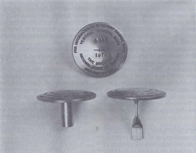
Figure 3.-NGS bench mark disk stamped with designation and year.
7. Sprinkle some dry cement on the exposed surface
of the disk; then rub it with a clean rag
using circular strokes. This will clean the disk
very nicely, removing all excess mortar from
its surface and recessed letters. Rubbing the
wet mortar around the edge of the disk in the
same manner will do no harm. On the contrary,
this is often done intentionally to finish
its surface and prevent cracking. Brush away
loose cement and make sure that the finished
product has a very neat appearance.
8. If there is a nearby crevice or spot of ground in
which a witness post can be conveniently set,
this should be done.
9. While the mortar is still wet, it must be covered
to prevent heavy rains from ruining its
surface and to conceal the disk from people
who might tamper with it. A piece of wood,
cardboard, heavy paper, or similar biodegradable
item will suffice.
10. The installation is not complete until all accumulated
trash has been picked up. Leave the
place in good order.
In setting a disk in a massive concrete or masonry
structure; first make sure the structure is
stable. Its foundation must extend to a depth that
equals or exceeds 25 percent of the specified depth
of the sleeve for the class A rod mark, as indicated
in table 2 (page 27). Furthermore, the foundation
must be at least as deep as the maximum depth of
frost penetration indicated on the map in figure 13
(page 34).
The disk can be mounted vertically in the wall
of a structure, but should always be set horizontally
if possible. The procedure for setting a disk
horizontally in a structure is identical to that for
setting one in bedrock. Make sure safety goggles
are worn when drilling into masonry or concrete.
Since for a vertical setting the hole for the disk's
shank must be drilled horizontally, the mortar
must be mixed separately. When drilling into
brick or other soft material, a hammer and star
drill should be used, rather than heavy power
equipment, to prevent extensive damage to the exterior.
The hole should be wetted before mortar is
put into it. After placing the shank of the disk into
the mortar filled hole, work it to the bottom edge
of the hole so that it will not settle askew while the
mortar is curing.
14
Class A Rod Mark
The class A rod mark is to be used whenever possible
where sound bedrock and substantially
stable structures are not available. The top of a
steel rod serves as the datum point. The rod itself
anchors the datum point to a stable stratum of
soil. In most areas a sleeve is required to isolate the
rod from soil movements occurring above the stable stratum.5 (See fig. 4.) This sleeve is omitted
where no soil movements are expected. At the surface
an encasement around the datum point provides
protection from impact and information to
the user. (See fig. 5.)
The rod is assembled from sections of 1.43-centimeter
(9/16-inch) type 316 stainless steel 6 coupled
with threaded studs of the same material. The
sleeve is made from 2.54-centimeter (1-inch)
schedule 40 polyvinyl chloride (PVC) pipe with
fittings to couple the sections. The annular space
between the rod and sleeve must be filled to prevent
water from infiltrating it. If water is allowed
to seep into this space, two problems will arise:
corrosion will occur; and when the water freezes,
stresses between the sleeve and soil will be transmitted
to the rod. The substance used as the filler
should be a grease or grease-like product with a
consistency that will remain soft at cold temperatures.
It must be insoluble in water, noncorrosive
to the rod and sleeve, and must have an extremely
long life expectancy.
The casement consists of a 12.7-centimeter (5-
inch) PVC pipe, 1/2-meter long, fitted with an
aluminum flange around its top edge. The flange
is imprinted with the standard information that
accompanies all bench mark monuments and is
stamped with the station's designation and year.
Its inside edge is recessed to accommodate a hinged
aluminum cover. This arrangement is placed around
the top of the rod, slightly below ground
level. Approximately 20 liters (2/3 cubic foot) of
concrete is then poured around it to hold it firmly
in place and to aid in recovery of the monument if
it becomes buried.
This type of monument has been designed to
prevent near-surface soil movements from changing
the bench mark elevation. The two major
kinds of movements it can counteract are frost
heave, and shrinking and swelling of expansive
soils. Averting these movements is accomplished
by extending the sleeve to the maximum depth to
which these soil movements are expected to occur.
Then the rod assembly, after being placed inside
the sleeve, is driven or pressed into the soil so that
it is anchored below the sleeve, and consequently,
below the layer of disturbance.
When frost heave can occur, the sleeve is placed
to a depth three times as great as the maximum
frost penetration indicated in figure 13 (page 34).
When any type of upright, such as a post, pile, or
pipe, is subject to frost action, the upward motion
caused by frost heave is normally greater than the
subsequent settlement after the ground has thawed.
Unless there is an opposing force, the object will
eventually be ejected from the ground. A sleeve
placed to three times the depth of frost will have,
in nearly all instances, enough friction between it
and the soil below the frozen layer to resist the
upward force of frost heave. In any case, the jacking effect of frost action will be retarded.
Consolidation of a soil mass can be counteracted
with this bench mark when it is placed to a sufficient
depth. As long as the sleeve isolates the rod
from the soil where consolidation (or rebound) can
have an effect, movement from this cause will not
change the bench mark's elevation. To be used
effectively in this manner, a geologist or soils expert
must determine where these movements
occur.
It is suggested that one of two methods be used
to place the 2.54-centimeter (1-inch) PVC sleeve,
though other methods might also prove effective.
(1) Where the soil is self-supporting, the cleanest
and quickest method is to use a small diameter,
conventional flight auger. Briefly, a hole is drilled
to the specified depth of the sleeve, the string of
augers used in drilling the hole is retracted, and
the sleeve is lowered into the hole. (2) Where the
soil is subject to caving, as in a loose dry sand, or
in working below the water table, a hollow-stem
auger can be used. The auger is drilled to the
specified depth, the bench mark sleeve is lowered
into place through the auger, and the auger is
retracted, leaving the sleeve in place.
When it is unknown whether or not a hole will
support itself, use the conventional flight auger.
If the hole caves before the bench mark sleeve can
be lowered into it, start over using a hollow stem
auger. Once some experience is gained in a particular
region, the mark setter will intuitively
know whether a conventional auger will likely
suffice or if efficiency would be lost in this trial-and-error method.
A suggested routine using the conventional
flight auger is given next. Some of the steps need
not necessarily be taken in the prescribed order.
Experience will dictate the most efficient manner
for a particular crew. One crew's method is pictorially
illustrated in figure 6 (pages 20-24).
| WARNING: Precautions must be taken before
drilling into the ground. Underground pipes
and cables can be damaged and can also cause
damage. to drilling equipment. Conceivably,
injury or death could result from drilling into
an electrical cable or gas line. (See "Safety,"
page 12.) |
5 Although it is somewhat detrimental from a corrosion
standpoint, the sleeve is normally essential for stability.
6 This alloy has the optimum combination of iron, nickel,
and chromium to combat corrosion in both weight loss and
pit depth, and yet remains economical.
|
15
Figure 4.-Sleeved class A rod mark.
16
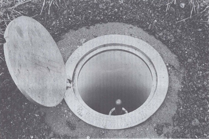
Figure 5.-Class A rod mark showing logo flange and hinged access cover.
17
1. Maneuver the drill into position with the rotary head situated over the spot where the
monument is to be placed. When the site is on
an incline, the vehicle should be facing uphill.
2. Level the vehicle with the stabilizing jacks. A
carpenter's level can be placed vertically against
the drill head mast to make sure it is
plumb both transversely and longitudinally.
3. Where neat landscaping must be preserved,
place a 2-meter square tarpaulin on the ground
and drill through a 1/2-meter hole cut in its
center.
4. Bore a hole 30 centimeters in diameter to a
depth slightly more than 1/2 meter for the
protective flanged encasement. This hole will
be filled with soil during subsequent operations,
but the objective is to loosen the soil in
preparation for setting the encasement.
5. Connect an appropriate bit to the first section
of a small diameter conventional flight auger
and begin drilling a hole to the required sleeve
depth. Depths for sleeves set within the continental
United States are specified in table 2
(page 27). Use figures 7 through 13 in conjunction
with this table to determine the depth.
Use the deepest depth indicated when a variety
of conditions exists. In regions outside the
conterminous States, the sleeve shall be placed
to a depth of 10 meters. Examples for determining
the depths are given in appendix E.
6. When the required depth is reached, pull the
augers straight up with no rotation to keep the
hole clean. Before removing the last section of
auger, clean the loose soil out and away from
the hole bored in step 4. After all the flights
have been retrieved, move the rotary drill head
off the axis of the hole to provide clearance for
the next steps.
7. Attach appropriate fittings to one end of a
2.54-centimeter (1-inch) PVC pipe to reduce
the inside diameter to 1.59 or 1.90 centimeters
(5/8 or 3/4 inch). Lower the pipe into the hole
with the reduced end down, then connect and
lower more sections of pipe as required. The
last section to be assembled must be cut to
length so that when the bottom of the hole is
reached, the top of the sleeve will be about 25
centimeters below the surface of the ground.
Finally, glue a female slip-to-thread adaptor to
the top of the sleeve. This will be used to make
connections to a grease pump for filling the
annular space with lubricant.
8. Assemble the 1.43-centimeter (9/16-inch)
stainless steel rod and lower it into the sleeve.
If a long, unwieldy length is required, the rod
may be coupled while it is being lowered into
the sleeve. To obtain tight joints, finger tighten
them and then apply one-quarter turn more.
9. When the rod assembly rests in the bottom of
the hole, it must be pressed or driven into the
soil beneath the sleeve. Alternately couple and
drive more sections of rod until it resists a
downward static force of 250 kilograms,7 but
make sure at least 1 meter of rod extends below
the sleeve. In clay, driving may be terminated
if the 250 kilograms of resistance are not met
after 10 meters of rod have been driven.
Care must be taken not to deform the end of
the rod being driven, or coupling of the next
section will be difficult. In the event refusal is
met before the minimum of 1 meter is driven,
the rod and sleeve must be pulled up, and the
hole must be drilled to the depth at which the
rod will ultimately be placed (1 meter below
the sleeve). New soil, soil mixed with cement,
or concrete must then be compacted in the
bottom of the hole to provide a good anchoring
material for the rod. In cases where soil mixed
with cement or concrete is used, extreme care
must be taken to prevent the sleeve from becoming
embedded in the anchoring material,
or movement of the sleeve will be transmitted
to the rod. One way to do this would be to
dump a layer of the original soil over the anchoring material to provide a buffer between
it and the bottom of the sleeve. If a large obstruction
makes it impossible to drill to the
required depth, the anchoring material must
be compacted in the bottom of the hole to a
depth 1 meter above the obstruction. Adjust
the sleeve length accordingly and take precautions
to isolate it from the anchoring material.
10. Provide the top of the rod with a suitable high
point on which a leveling rod can be supported.
This may be done in one of three ways. (1)
When the depth to which the rod will be driven
is known in advance, use a prerounded top
section for the last length of rod to be coupled.
(2) Cut off the rod when the proper depth is
reached and round the top with a file. Or (3)
crimp a type 316 stainless steel cap with a
hemispherical end onto the top of it.
7 The 250-kilogram resistive force can be determined in.
directly by relating dynamic resistance to driving rate. Ignoring
energy losses, the work done in driving the rod equals
the energy output of the driving equipment. For a drop
hammer, the Resistance offered by the soil times the set
(penetration per blow) equals the Weight of the hammer
times the Height from which it was dropped (Rs = WH). For
a gasoline powered impact hammer, the Resistance times
the set equals the effective Energy output of the impact
hammer (Rs = E). Since the ultimate bearing capacity under static load is usually many times the driving resistance,
this relationship will yield conservative results if R is set to
250 kilograms.
|
18
11. Pump the filler into the annular space between
the rod and sleeve, making sure no voids are left. Approximately 1/3 liter (0.1 gallon) of
filler is needed for each meter of sleeve. During
this operation, the sleeve may have to be
lifted slightly to allow air to escape from its
bottom. When the entire space is filled, place
a 1.43-centimeter (9/16-inch) ID (inside diameter)
X 2.54-centimeter (1 inch) OD (outside
diameter) "0" ring or rubber bushing
around the rod inside the top of the sleeve just below
the adaptor. This will serve to steady the
rod for the process of differential leveling. It will
also stabilize the rod horizontally in the
event the mark is someday used also for horizontal
control.
12. Backfill the hole around the bench mark sleeve
with soil. Much of the soil brought to the
surface during the drilling of the hole can be
disposed of in this manner. Make sure the
sleeve gets firmly impacted in the hole in case
the monument is eventually used also for horizontal control. In areas subject to frost heave,
it is desirable to use a clean sand in the upper
end of the hole to the depth of maximum frost
penetration.
13. Clean the soil out of the 30-centimeter hole
around the bench mark sleeve to a depth of
about 30 centimeters. Place a 1/2-meter length
of 12.7-centimeter (5-inch) PVC pipe around
the rod and sleeve so that they are centrally
located within it. Press or drive the pipe down until
its top edge is about 5 centimeters below
the surface of the ground and 10 centimeters above
the top of the rod. Fill the protective
pipe around the sleeve with soil until about 2
to 4 centimeters of the sleeve and 10 centimeters of the rod are exposed.
14. Stamp the bench mark designation and year in
the area provided on the aluminum flange
supplied for the top of the protective PVC
pipe. Then fit the flange and cover over the
pipe.
15. Mix about 20 liters of concrete, the approximate amount produced by the commercially
available 36-kilogram (80-pound) bag of pre-mixed concrete. Pour the concrete around the
pipe and flange and tamp it into place. Finish
the surface of the concrete so that it is flush
with the top surface of the flange and it slopes
gently away from it. This is important because
no exposed edges will be left to facilitate removal of the flange, and water will drain away
from the access cover rather than into it. Remove excess concrete from the flange and be
sure the imprinted information is not defiled
with concrete.
16. Set a witness post when appropriate.
17. Before leaving the area, clean it up. Scatter or
otherwise dispose of any leftover soil from the drilled holes. Pick up trash which has accumulated
during the installation. Finally, set a
temporary covering over the wet concrete to
shelter it until it cures.
The procedure for placing a sleeved bench mark
using hollow-stem augers is nearly the same, with
the following exceptions:
1. After boring the 30-centimeter hole for the encasement, attach an appropriate cutterhead to the first section of a small diameter, hollow-stem auger. At the time of this writing, the smallest known available size has a 5.7-centimeter (2-1/4-inch) ID and a 12.7-centimeter (5-inch) OD. Fit the cutter head with a disposable knockout plug. Plastic is preferred to a wood plug which could swell when used in a wet environment, making its removal difficult. Never use a metal plug unless it is type 316 stainless steel. Contact of dissimilar metals in the completed installation must be avoided.
2. Drill to the required sleeve depth in such a manner as to bring as little soil to the surface as possible. This is accomplished by combining proper speeds of rotation and feed to obtain a screwing effect rather than a boring effect, and by halting rotation immediately after the drill head has reached the bottom of the feed stroke.
3. Retract the string of augers about 1/4 meter and secure them with an auger fork. Disconnect the augers from the rotary drill head and move the head off the axis of the hole to provide clearance for lowering the sleeve.
4. Assemble and lower the 2.54-centimeter (1-inch) PVC sleeve into the hollow stem of the auger string. To knock out the disposable plug in the cutter head, lift the assembled sleeve about 2 or 3 meters and let it drop. When working below the water table, cohesionless soils at the bottom of the hole can sometimes be washed up inside the hollow stem by pressure of water outside the augers. To prevent this, fill the inside of the auger with water to at least the height of the water table before the plug is knocked out.
5. Retract the string of augers by reversing the rotation of the drill head and lifting it with the pullout mechanism. With the appropriate combination of rotation and pullout speeds, excess soil that was brought to the surface can sometimes be returned and compacted around the bench mark sleeve.
6. Assemble and lower the stainless steel rod as before and complete the remaining steps as listed in the procedure for using the conventional flight auger.
19
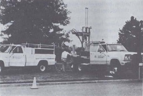 |
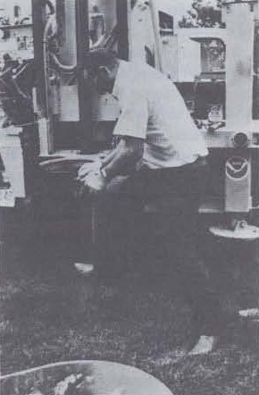 |
|
1. Drill rig maneuvered into position and leveled.
|
2. Digging through the sod.
|
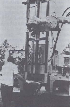 |
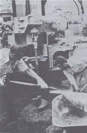 |
|
3. Preparing to attach a large auger.
|
4. Boring a hole for the protective casement.
|
|
Figure 6.-Setting a sleeved class A rod mark.
20
|
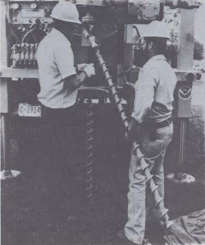 |
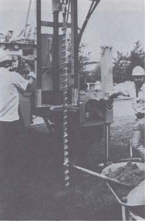 |
| 5. Attaching a length of conventional flight auger. |
6. Drilling a hole for the sleeve.
|
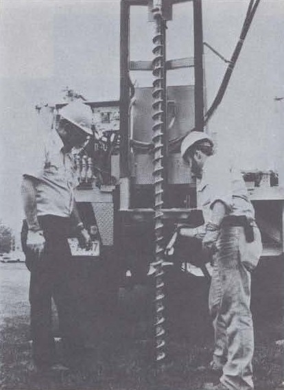 |
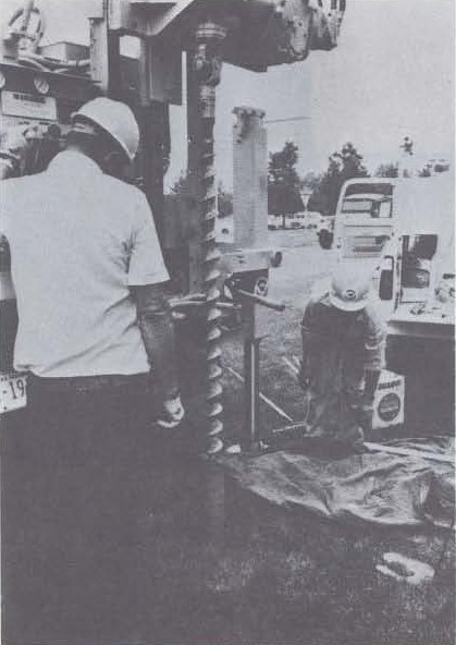 |
|
7. Retracting the flight augers.
|
8. Retracting the lower sections of flight auger.
|
|
Figure 6.-Continued.
21
|
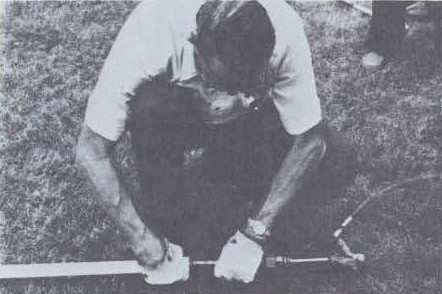 |
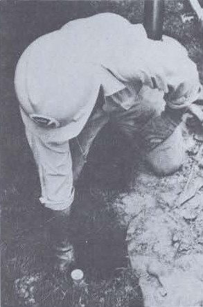 |
|
9. Pumping filler into the sleeve.
|
10. Sleeve lowered into the hole.
|
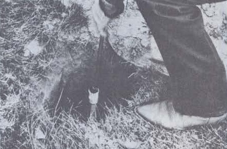 |
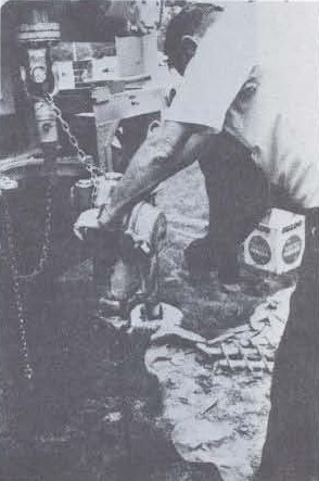 |
|
11. Lowering the rod into the sleeve.
|
12. Driving the rod into soil beneath the sleeve.
|
|
Figure 6.-Continued.
22
|
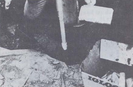 |
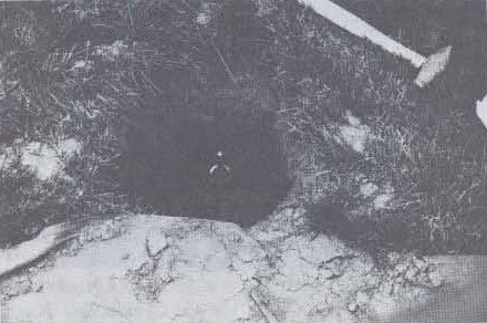 |
|
13. Filling soil in hole around the sleeve.
(Sleeve temporarily extended to keep dirt out.)
|
14. Sleeve and rod in place.
|
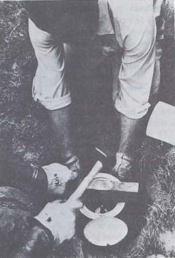 |
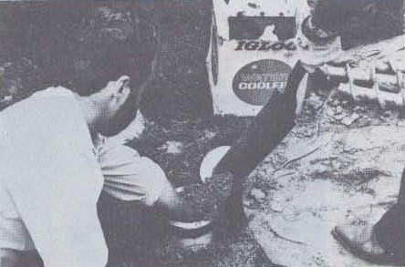 |
|
15. Driving the protective pipe into place.
|
16. Filling soil inside the protective pipe.
|
|
Figure 6.-Continued.
23
|
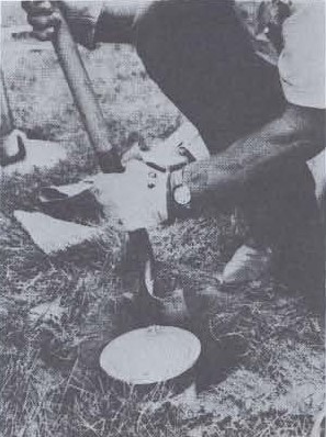 |
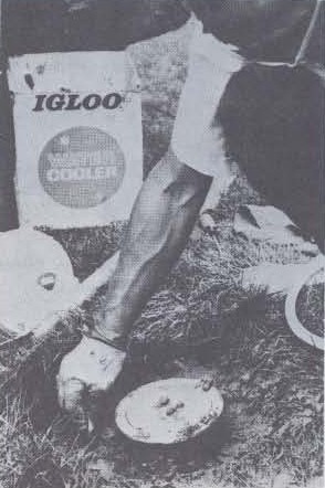 |
|
17. Preparing the hole for concrete.
|
18. Working concrete around the
protective pipe and logo flange.
|
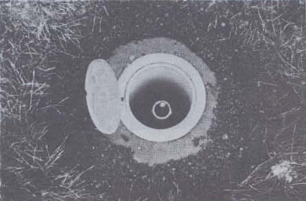 |
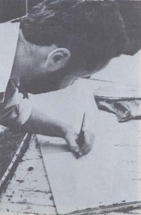 |
|
19. The completed bench mark.
|
20. Writing the description.
|
|
Figure 6.-Continued.
|
24
In some situations, unexposed bedrock will be encountered before the required bench mark sleeve depth is reached. If drilling is halted by an underground
obstruction, note the depth of the obstacle,
move the equipment a few meters, and try drilling
again with a conventional flight auger. If the obstruction
is once again encountered at roughly the
same depth, it is likely to be bedrock. The class A
rod mark can be set to a depth less than normally
required if one of the holes is 4 meters or more in
depth. If both holes are less than 4 meters, another
try must be made or another site located.
Once it has been established that there is probable
bedrock at a depth of 4 meters or more, a rod
type bench mark can be set. Where the soil is self-supporting
and the desired hole stays open, backfill
it with concrete or soil for 1 meter above the
bedrock. If the hole has caved, redrill it with a
hollow-stem auger to a depth 1 meter above the
bedrock. Place the sleeve into the hole as usual
making sure it does not become fixed to the concrete
in the bottom, if used. Before placing the
rod, cut its bottom section off so that when pressed
or driven to the bedrock, its upper end will be
about 15 centimeters below ground level. The remaining
steps are identical to those for placing the
usual sleeved rod mark. (See pages 18-19.)
To anchor the rod into the underground bedrock
would be desirable but not absolutely necessary.
Total vertical motion at any particular depth
results from the accumulation of incremental
changes below it. Accumulation begins at the level
where movement is nonexistent and the surface of
bedrock delineates the level where no soil movement
occurs. Since the rod will be exposed to the
soil for only 1 meter above that depth, only the
activity accumulated over a 1-meter depth starting
from zero movement will be transmitted to the
rod. This amount is negligible.
Where the soil is nonexpansive and the maximum
depth of frost penetration is less than 1/2
meter as determined in figures 7 through 13, no
sleeve is required for the class A rod mark. The
setting procedure is simple.
1. Maneuver the drill rig into position and level
it.
2. Bore a hole 30 centimeters in diameter to a
depth slightly greater than 1/2 meter to accommodate
the protective flanged encasement.
3. Press or drive the rod to its required 4-meter
depth. In areas where this is made difficult due
to the existence of hard clay, scattered stones
or cobbles, or frost, a hole can be drilled to a
depth of 3 meters, maximum. The rod can be
placed in the hole and pressed or driven another
meter so its top is about 15 centimeters
below ground level. Then the hole is backfilled.
4. Fabricate the protective encasement, set a witness
post, and clean up as with installing the
sleeved class A bench mark.
This mark can also be set with an ordinary post
hole digger and gasoline powered hammer. First,
the 30-centimeter hole is dug. Then the sectional
rod is driven and connected, one length at a time.
And finally, the protective casement is constructed
and the remaining steps taken as indicated.
Class B Rod Mark
To perpetuate the National Vertical Control
Network with monuments of only the most stable
nature would be ideal, but other factors make this
impossible. Situations will be encountered where
bedrock or other stable settings are not at hand,
and where the soil is unstable but the equipment
required to set the sleeved rod mark is unavailable.
Among others, mark maintenance personnel, who
relocate monuments which are destined for destruction,
and those who set tidal bench marks
for the Office of Marine Surveys and Maps, National
Ocean Survey, need an alternative to the
sleeved class A rod mark.
The class B mark consists of a stainless steel rod
assembly driven to a depth based on soil and
weather conditions, and capped with the standard
bench mark disk. It has no sleeve. A casement at
the surface protects the monument from damage
by impact. This casement differs from the flanged
encasement for the class A rod mark in that a PVC
clean-out plug is used in place of the logo flange
and access cover. The bench mark disk carries the
logo and designation. Except where soil movements
are nonexistent, these marks cannot be expected
to hold their elevations as well as the class
A rod marks. The procedure for setting a class B
rod mark is as follows:
1. Dig a 30-centimeter hole to a depth slightly
greater than 1/2-meter for the protective
casement.
2. Taking care not to deform its end, drive the
first section of 1.43-centimeter (9/16-inch)
stainless steel rod down to just above ground
level. Make sure it remains plumb while driving.
Couple another section of rod tightly to
the first and drive the assembly down as before.
To obtain tight joints, finger tighten them and
then apply one-quarter turn more. Repeat this
procedure until the required depth is reached
as indicated in table 3 (page 27). When a variety
of conditions occur, use the deepest depth
specified. In clay, however, the depth may be
limited to 10 meters. Drive the last section down
to about 10 centimeters below ground level.
Every effort must be made to reach the minimum
depth specified. If firm resistance is met
before the required rod depth is nearly approached,
discontinue driving before the rod
becomes tightly embedded in the resistant
layer. Using a pipe wrench to rotate the rod clockwise while simultaneously pulling up on
it, try to pull it out so the installation can be
attempted in another spot. When firm resistance
is met at nearly the required rod depth,
continued driving will probably result in
reaching that depth. Drive with determination;
as long as the rod keeps going down, no
matter how slowly, keep at it. If the required
depth is not reached after exhaustive efforts,
cut the rod off about 10 centimeters below
ground level and use as is.
25
3. Stamp the designation and year on the bench
mark disk and crimp the hollow shank on the
disk onto the top of the rod.
4. Place a 10.2- or 12.7-centimeter (4- or 5-inch)
PVC pipe 1/2 meter in length around the disk
and rod. Press or drive the pipe down until its
top edge is about 5 centimeters below ground
and 5 centimeters above the disk. Fit the top
of the pipe with the proper size slip plug or
threaded plug with appropriate female
adaptor.
5. Mix about 20 liters of concrete to place around
the top of the protective pipe. Twenty liters is
the approximate amount produced by the commercially
available 36-kilogram (80-pound)
bag of premixed concrete. Pour concrete
around the pipe and tamp it into place. Finish
the top surface of the concrete so that it slopes
gently downward and away from the top of the
pipe. This is important because it will help
drain water away from the protective pipe
rather than into it.
6. Set a witness post when appropriate.
7. Before leaving the area, clean up any trash
that accumulated during the installation. Finally,
set a temporary covering over the
whole arrangement to protect it until the
concrete cures.
Miscellaneous Marks
Occasionally, a natural or readymade bench
mark setting will exist that would be more stable
than a rod mark but which cannot accommodate a
brass disk. An example is a deep well casing. It
would resist not only near-surface movements, but
also, to a degree, movements originating in the
subsurface such as subsidence from pumping. A
good illustration of this can be seen in Santa Clara
Valley, Calif., where well casings project prominently
because of ground subsidence. These settings
should not be passed by simply because disks
cannot be mounted on them. They can furnish excellent
references for elevations, provided they extend
at least three times as deep as the required
sleeve depth for a class A rod mark in that area.
It is important to select a good point of reference
for the elevation of this type of bench mark.
A prominent protrusion can be used if it is definite
and has a good high point on which to rest the
leveling rod. Alternatively, a cross can be etched
with deep fine lines on a spot accessible to a leveling
rod or tape. If possible, stamp or etch the
bench mark designation and year nearby.
26
Table 2.-Sleeve depth for class A rod mark set within
the continental United States
|
| Condition |
|
Extent of occurrence |
Depth |
|
| Soil volume change a |
{ |
nonexpansive |
no sleeve required b |
| low expansive character |
6 meters X CF c |
| medium or high expansive character |
10 meters X CF c |
| |
|
|
|
| Active frost penetration d |
{ |
maximum 0.5 meter or less |
no sleeve required b |
maximum greater than 0.5 meter
|
3 X max frost penetration |
| |
|
|
|
| Permafrost e |
|
any extent |
10 meters |
a Categories of expansiveness are shown on the maps in figures 7 through 11. Inability to accurately
delineate category boundaries necessitates assumption of the greater expansive character
when working near a boundary. A consolidated map of these figures, at a larger scale, in color, is
available by writing to the USAE Waterways Experiment Station, P.O. Box 631, Attn: GEO, Vicksburg,
MS 39180. It is entitled Occurrence and Distribution of Potentially Expansive Materials in the
United States.
b Where no sleeve is required, the rod assembly shall be set to the depth at which a static load of
250 kilograms causes no movement (see footnote 7, page 18) but at least 4 meters.
c The Climate Factor (CF) is indicated on the map in figure 12. Use the larger value when there
is doubt as to what value applies to a particular site.
d Depth of maximum frost penetration is indicated on the map in figure 13. Use the upper
limit for each area delineated.
e For an excellent overview of permafrost areas, consult Ferrains (1965).
|
Table 3.- Minimum depth for class B rod mark a
|
| Condition |
|
Depth |
|
| Nonexpansive soils |
|
4 meters |
| Soils of low expansive character |
|
5 meters X CF |
| Medium or highly expansive soils |
|
6 meters X CF |
| Low penetration resistance b |
|
To substantial resistance c |
| Seasonal frost penetration |
|
4 X maximum frost penetration d |
| Permafrost |
|
2.5 X maximum depth of active frost layer |
a Footnotes a, c, d, and e from table 2 also apply here.
b A static load of 250 kilograms will move the rod.
c Substantial resistance is indicated when a static load of 250 kilograms will not move the rod (see footnote 7, page 18).
d The minimum depth shall be 4 meters.
|
27
Figure 7.-Distribution of potentially expansive materials, Northeastern States.
28
Figure 8.-Distribution of potentially expansive materials, Southeastern States.
29
Figure 9.- Distribution of potentially expansive materials, North-Central States.
30
Figure l0.-Distribution of potentially expansive materials, South-Central States.
31
Figure 11.-Distribution of potentially expansive materials, Western States.
32
Figure 12.-Climate Factor (CF), adapted from Building Research Advisory Board (National Academy of Sciences 1968).
33
Figure 13.- Extreme depth of frost penetration (in meters).
34
5. DESCRIPTIONS
Descriptions are an important product of geodetic
leveling because the utility of the vertical
control network depends largely on how effectively
they facilitate bench mark recovery. Consult the
NOAA Manual, Geodetic leveling (Berry 1978),
in preparation at the time of this writing, for detailed
instructions on how to write descriptions.
If this is not available, Special Publication No.
239, Manual of geodetic leveling (Rappleye 1948),
also contains some valid information. General
guidance for describing a monument is given here.
In NGS, geodetic data, including descriptions, are
stored, manipulated, retrieved, and sometimes disseminated
by computer. Consequently, descriptions
must be submitted in proper computer-readable
form for inclusion with NGS vertical control
data. Consult chapter 7 of Input Formats and
Specifications for the NGS Data Base (NOAA 1977)
for acceptable format.
The text of the description provides information
needed to locate a bench mark. It must be clear
and concise, first leading the reader to the general
vicinity of the monument, then to the exact spot.
Directions should start from a highway intersection
or prominent landmark in the nearest city
shown on an official state highway map.
Unless the bench mark is very near the starting
point, distances are first given to the nearest tenth
of a mile (or kilometer). The nearer the monument
is approached, the more refined the measurements
become, going from miles and tenths, to tenths of
a mile, to feet and tenths (or kilometers and tenths,
to tenths of a kilometer, to meters and tenths). As a
rule, give distances in order of decreasing magnitude,
but the final reference measurements should
be made in the order which lends most conveniently
to recovery. For example, if a monument is
located 2.6 meters from the corner of a building and
5.4 meters from a fence, it should be stated in that
order because the building would be spotted first.
Distances must usually be accompanied by directions
to 8 points of the compass (i.e., north, northeast,
east. . .). Where confusion could result with
only 8 points, 16 points of the compass may be used
(i.e., east, east-southeast, southeast. . . ).
Do not record numeric data with more significant
digits than those with which they were obtained.
The number 2.90 does not imply the same
meaning as the number 2.9. The former refers to a
value between 2.895 and 2.905, which is accurate to
the nearest hundredth of a unit. The latter refers
to a value between 2.85 and 2.95, accurate only to
the nearest tenth.
All bench marks to be included in the national
network must be referenced with consistent techniques, or misinterpretation of some descriptions
will result. Distances between reference objects
and monuments should nearly always be measured
horizontally or mathematically reduced to a horizontal
distance. In special circumstances where
great convenience results, a sloped distance may
be recorded in the description, but it must be
labeled as such. Distances not labeled as "sloped"
are always assumed to be horizontal. For an angle
of 30°, the difference between a horizontal distance
of 10 meters and its sloped counterpart is
more than a meter. A discrepancy of this magnitude
can result in considerable loss of time when
searching for a buried monument, especially if
the lines-of-position intersect at a shallow angle as
shown in figure 2 (page 8). Furthermore, a distance
measured from a line, such as a fenceline or
centerline, should always be measured perpendicularly
to that line.
The origins of measurements must be clearly
defined in all cases except the following two,
where by convention they are inferred. (1) At the
junction of two or more roads, the origin will be
assumed to be the intersection of the centers of the
roads unless specifically defined otherwise. "The
intersection of U.S. Highway 29 and State Road
120" means the intersection of their centers. (2)
Measurements are assumed to be from the center
of objects such as utility poles. Where another
position is desired for the starting point, it should
be noted (e.g., "4.5 meters southeast of the southeast
edge of telephone pole number 258").
Good descriptions are very important. Some
bench marks are not recovered and used for many
years after they are set. During this time heavy
vegetation can grow up around the monument,
making recovery difficult and time consuming.
Objects used as reference points can be moved or
destroyed. Good judgment and foresight are
needed in referencing the mark and writing the
description.
35
APPENDIX A.-
APPROXIMATE CONVERSION TABLE: METRIC TO ENGLISH UNITS
| 1 millimeter |
= 0.039 inch |
| 1 centimeter |
= 0.39 inch |
| 1 decimeter |
= 3.9 inches |
| 1 meter |
= 3.3 feet |
| 1 kilometer |
= 0.62 mile |
| 1 liter |
= 0.26 gallon |
| 1 liter |
= 0.035 cubic foot |
36
APPENDIX B.-
EXCERPT FROM U.S. LAKE SURVEY MISCELLANEOUS PAPER 68-6, THE USE OF GEOPOTENTIAL HEIGHTS FOR GREAT LAKES VERTICAL DATUM, BY CARL B. FELDSCHER AND RALPH MOORE BERRY, LAKE SURVEY DISTRICT, DEPARTMENT OF THE ARMY, U.S. CORPS OF ENGINEERS 8
This discussion deals in general with a subject
that the average civil engineer, without any geodetic
orientation, would think of as "levels." This
average engineer, having been exposed to the subject
through a course in "basic surveying," is inescapably
inclined to think of "levels" as the process
of determining "elevations," in the context of a
summation of vertical "height differences" above
some arbitrary "horizontal" plane assumed as a
datum.
If the purpose of "levels" is merely to provide
reference for setting of pavement forms, or any
other type of construction of moderately limited
extent, this first intuitive concept is adequate;
witness the fact that the average sewer undeniably
manages to flow "down hill." But if the purpose
of "levels" is to provide vertical control over a
relatively large area, or of higher accuracy than
that required in ordinary construction, additional
considerations must be introduced.
The first additional consideration to be introduced
is the well-known fact that the earth is not,
in fact, a plane surface. Even the engineer with
only a basic course in surveying is willing to concede
this point. However, the nature of this surface
involves some moderately subtle concepts that are
not immediately apparent.
For example, many people are willing to accept
a sphere as being a suitable geometrical figure of
the earth. This, however, can lead to some patent
absurdities if carelessly applied to the principles
of levels. There is the case of the flow of the Mississippi
River. Considering the 1535 kilometer
section from the mouth of the Ohio River (Cairo,
Illinois) to Head of Passes, Louisiana, engineer's
levels indicate that the mid-stage elevation of the
water surface drops approximately 91 meters. (See
fig. 14, this manual.) This agrees with common
sense but, to the unwary, is a bit difficult to reconcile
with the fact that Head of Passes is 2643 meters farther from the center of the earth than the Mississippi
River is at Cairo, Illinois. This could lead
to the conclusion that the river is running uphill
at a rate of 1.7 meters per kilometer, instead of
downhill at a rate of 6 centimeters per kilometer.
(The explanation of this absurdity lies in the fact
that the meridional section of the earth is approximately
elliptical.)
This can, of course, be countered by the engineer
with the statement that he never meant for his
levels to define the distance of a point from the
center of the earth. When pressed for another definition,
he will mutter something about height
above "Mean Sea Level." This can, however, be an
elusive concept unless carefully defined. There is
not much difficulty with the definition at any
single point on an unobstructed ocean shoreline.
Here, we are told, mean sea level will be revealed
as the average height of the water over the 19-year
period that is required for the earth and moon to
go through their entire cycle of combinations that
produce the tides. This concept is simple in principle
even though a bit difficult to implement.
Even the generalization that Mean Sea Level must
be the surface defined by a number of such points
is not difficult until faced with the theoretical
proposition of just what is meant by Mean Sea
Level when it is used as a reference to define the
"elevation" of a point far inland and high above
the level of the ocean. (See fig. 15, this manual.)
The usual explanation for this is that Mean Sea
Level is the surface that would be generated if all
the continents were criss-crossed with a number of
narrow canals extending from ocean to ocean, admitting
ocean water without causing any currents
and without diminishing the quantity of water in
the oceans.
Accepting this concept, the question immediately
arises as to just what is the actual shape of
this Mean Sea Level surface, and this leads back to
the questions originally brought out. Isaac Newton
in his Principia, first published in 1687, made
substantial contributions to the theory of the attraction
of gravity and concluded that the figure
of the earth is that of an ellipsoid of revolution.
8 Presented at Army Science Conference, U.S. Military
Academy, West Point, New York, June 1968. The U.S. Lake
Survey was abolished in 1976. Some functions were transferred to the National Ocean Survey, NOAA
|
.
37
Figure 14.-Mississippi River flows uphill.
Figure 15.-Elevation.
38
Figure 16.-Geodetic reference ellipsoid.
Figure 17.-The geoid.
39
This was based strictly on a mathematical derivation,
with certain assumptions made about homogeneity.
This was subsequently substantiated by
the measurements made by the French mathematicians
Picard, Clairaut, Bouguer, Maupertuis,
Cassini et al. (Todhunter 1873) considered to be the
beginning of modern metrical geodesy, in the
interval 1669-1735-1743.
The figure generated by rotating an ellipse about
its minor axis is generally adopted by geodesists
today as an acceptable approximation to the shape
of the sea-level surface but it must be understood
that this is actually only a mathematical model on
which the calculations of geodetic positions can be
carried out with sufficient accuracy for most work.
The adoption of this geometrical shape is actually
a compromise with expediency, because of the use
of other more complicated shapes would enormously
increase the complexity of calculations. The dimensions of the reference ellipsoid in actual
use vary throughout the world, with, as might be
expected, different figures being used in North
America, Europe, Russia, etc. (See fig. 16, this
manual.)
The actual shape of the Mean Sea Level surface,
however, is not readily amenable to description
by a simple mathematical expression. If the waves,
tides, currents, etc., be "averaged out" and the sea
level surface considered to be the quiet, undisturbed,
smooth surface of the sea, a liquid in
equilibrium, it will be immediately obvious that
this surface will be everywhere normal to the
direction of gravity. This is indeed the definition
of the Mean Sea Level surface even when it is extended
underneath the surface of the continents. Further consideration will reveal that this is an
equipotential surface. Whatever its shape, the
technical name assigned to the particular equipotential
surface that is defined by mean sea level
(where available) is the geoid. If the earth were a
homogeneous body, or if density varied systematically
with distance from the center of the earth,
the geoid would be a smooth surface of revolution,
closely approaching an ellipsoid. Since, as is well
known, the mass distribution within the earth is
not systematic, the surface of the geoid does approach
an ellipsoid as the simplest "best fit"
figure, but it is actually an undulating surface,
sometimes above and sometimes below the mathematical
figure. (See fig. 17, this manual.) Since the
level bubble in a surveying instrument indicates
a perpendicular to the local direction of gravity,
the surface of reference in leveling is actually the
geoid and not the geodetic ellipsoid.
40
APPENDIX C.-
SOILS
Elementary knowledge of soil classifications and
terms is necessary to understand the information
presented in this manual. Terms used by the layman
and expert alike carry many connotations and
can cause considerable confusion. Technical classifications
can even be confusing in that a variety
of classification systems have been devised, each
for a different use. A synopsis of soil classification
and explanation of some of the more common soils
terms are set forth below.
To the engineer the term soil generally refers to
an unconsolidated mixture of discrete particles
interspersed with gasses and liquids, which lies
above bedrock. No fine line can be drawn between
soil and bedrock without arbitrarily defining bedrock
in terms of physical properties such as compressive
strength or degree of consolidation. There
are an infinite number of phases between the hardest
rock and the loosest soil. For the purpose of this
manual, it will suffice to call bedrock any extensive,
hard, earthen material which cannot be
penetrated without a diamond or tungsten carbide
tipped drill bit. Soil includes the materials formed
by mechanical disintegration and chemical decomposition
of bedrock.
Soils are divided into two groups called organic
and inorganic. Organic soils are those which contain
an appreciable amount of decayed plant or
animal matter. They can be identified by their
dark color and distinctive odor resulting from the
decomposition of the organic matter. Large deposits
of these soils form peat bogs, muskeg, and
swamps, but they also overlie other soils in an
often thin layer of humus. The main disadvantage
of organic soils from an engineering standpoint is
their high compressibility. A load placed on this
type of soil is subject to excessive settling.
Inorganic soils are distinguished from one
another by a number of criteria, the most important
being texture. Texture is mainly a reflection
of grain size, but it is also influenced by particle
shape. Soils may be grouped on this basis into
four classes-clay, silt, sand and gravel. The size
limits for these particles are as follows: 9
| clay |
less than 0.005 mm |
| silt |
0.005 to 0.05 mm |
| sand |
0.05 to 2.0 mm |
| gravel |
greater than 2.0 mm |
Sands and gravels are often referred to as coarse-grained or granular soils. They are cohesionless
and the individual particles can be distinguished
with the unaided eye. Accordingly, visual inspection
of a soil sample to determine whether or not
it is coarse-grained is the first step infield identification.
For the purpose of mark setting, it is not
necessary to distinguish between sand and gravel. Both are very good soils in which to set monuments.
Clays and silts are fine-grained materials. Their
individual particles cannot be differentiated with
the unaided eye. Normally, particles of this size
are flat and plate-like rather than rounded, and
due to this the soils are usually cohesive. The
degree of this characteristic gives an indication of
grain size and can therefore be used to determine
whether a soil contains mostly clay or mostly silt.
By varying its water content, a clay can be made
into a consistency where it can be deformed rapidly
without cracking or crumbling, exhibiting a
property called plasticity. A clay can be rolled into
long thin threads without breaking, and upon air
drying it will have considerable strength. Silts
can also be rolled into threads but when held by
its end, a silt thread which is more than about 10
centimeters long will break. Unlike clay, a small
amount of air-dried silt can easily be crushed with
the fingers. If enough water is added to a pat of
silt to make its consistency like that of a thick
paste, and this pat is shaken in the palm of the
hand, it will appear wet and shiny. If the pat is
then squeezed, the surface moisture will disappear
and the pat will eventually crack. Clay, on the
other hand, will remain unchanged when handled
in such a manner.
9 Some systems use 0.002 and 0.074 mm to distinguish between clay and silt, and silt and sand respectively.
|
41
A soil mass consisting mainly of a limited range
of particle sizes is said to be uniform. More often,
soils contain appreciable amounts of many different
particle sizes, frequently including all
four of the major classes (i.e., clay, silt, sand, and gravel). These are called mixed soils. They are
described by naming the two most predominant
constituents, the one of lesser abundance qualifying
the greater. For example, a silty sand might
contain 60 percent sand-sized particles and 30
percent silt-sized particles. The remainder would
be clay or gravel or both.
Another way to qualitatively describe a coarse-grained
soil is with the term clean. A clean sand or
gravel does not contain an appreciable amount of
fines (particles less than about 0.1 millimeter).
Locations with these types of soils provide excellent sites for setting bench marks.
A description of soil is not complete until some
indication is given as to its natural condition.
Granular soils may be loose or dense. Fine-grained
soils are described by their consistency, which can
be soft, medium, firm, stiff, or hard. A simple test
can be employed to determine the consistency by
pressing the fist, thumb, or fingernail into the soil
and gauging the resulting penetration. In addition,
one of the most significant conditions of a soil
mass is described by its drainage characteristics.
Good drainage is indicated with a sloping topography
to facilitate the removal of surface water,
granular soil particles which allow water to percolate
through, and a water table not too near the
surface. It is desirable to locate bench marks in
soils with good drainage.
42
APPENDIX D.-
EXISTING MONUMENTATION IN THE VERTICAL NETWORK
Since the beginnings of precise geodetic leveling
in the United States in 1877, and the subsequent
formation of the Coast and Geodetic Survey in
1878, a variety of different types of bench marks
have been established in our National Vertical
Control Network. For the most part, they were
appropriate for their times, but according to today's
high standards, they have various shortcomings
and are no longer to be set. Many of the
monuments, to be sure, were set in such a manner
as to have maintained their positions very well. In
any event, they do comprise the major portion of
the network.
The first bench marks were placed at intervals
of from 5 to 15 kilometers. They were established
on structural members of buildings, dams, aqueducts,
bridges, locks, piers, culverts, arches, and
pedestals; on granite, marble, or cedar posts; and
in bedrock and boulders. Some of them had no
physical markings for the exact elevation reference
point, but were defined descriptively by phrases
such as "centre of the sill," "top of a post," and
"northwest corner of the top surface." Others were
marked with chiseled square or circular cavities,
centers of triangles, crosses, lines, bolts, and rectangular
metal plates.
Early in this century, precast concrete posts, 1 to
2 meters in length and, in a few instances, 1-meter
lengths of pipe began supplementing the stone
posts. Along with this development, bronze tablets
came into use. The disks were a major improvement
over the chiseled squares and other markings
in that they provided a more definite high
point to support the leveling rod and were more
clearly visible to a person searching for the bench
mark.
Cast in place concrete monuments were introduced
in the latter half of the 1930's. The procedure
for setting them started with digging a hole
about 30 to 35 centimeters in diameter to a depth
of about 1 meter or below the frost line. The better
monuments were cast in tapered holes with a
smaller diameter at the top. The bottom of the hole
was then extended and enlarged to provide greater
resistance to heaving and settling. A form was set
in place for the top of the mark and sometimes for
the entire length of it to make its sides smooth,
thereby lessening the effect of frost heave. Casting
posts in place eliminated the work required to
manhandle the heavy precast posts, which consequently
were phased out completely in the
1940s.
In 1954, the Coast and Geodetic Survey began
experimenting with the copperclad steel rod mark.
Until this time, bench mark settings had been
limited to two basic types: structures and posts
(or pipes). Bench marks in structures have
generally held their elevations well. When foundations
are investigated to the extent directed in this
manual, they will be even more reliable. Concrete
or stone posts, however, are excessively vulnerable
to the forces of nature. Frost heave jacks them up,
expansive soils cause them to "float," and their
own weight makes them settle. If they are located
in well-drained, coarse-grained soils, they make
very good bench marks, but anything resistant to
impact and corrosion will suffice in these areas.
Disks have had relatively few changes through
the years. Most of them have been made of brass
or bronze. The tops have been about 8 to 10 centimeters
in diameter and spherically shaped. Irregularly
shaped shanks have served as anchors to
secure the tablets in drill holes. The earlier tablets
were cast in one solid piece. Later the shank was
fabricated separately and silver soldered to a disk
which was cut and pressed from sheet stock. Legends
have varied little. They indicated the organization
which established the mark (i.e., Coast and
Geodetic Survey, National Ocean Survey, or National
Geodetic Survey), the type of mark (i.e.,
bench mark, tidal bench mark, or vertical control
mark), whom to write for information (i.e., The
Director and organization, Washington, D.C.) and
a phrase warning against vandalism.
Changes occurred to the disks during the following
time periods: (1) From 1934 until 1956, the
adjusted elevation was stamped on the disk as a
matter of standard procedure. This was a very
poor practice because both movements of the
monument and readjustments of the network
caused many of the stamped elevations to be erroneous.
(2) For a short time during and immediately
after World War II, cast iron was used
because brass and bronze were in short supply.
A considerable number of these disks corroded to
such an extent that the precise datum point was worn down and the logo became illegible. Brass or
bronze disks make good bench marks when set in
substantial structures of concrete or masonry. An
improvement could be made, however, by providing
the upper surface with a protuberance to define
a more precise datum point. Flat disks should
never be used for bench marks.
43
In 1955, the Coast and Geodetic Survey began
installing rod type bench marks. They consisted of
5/8-inch copper-clad steel rods in 5-, 8-, and 10-
foot sections driven to refusal or some maximum
depth. The required rod depth was attained by
joining threaded ends of rod sections with brass
couplings. Some of these marks have been driven
to depths well in excess of 30 meters. A brass bench
mark disk with a tubular stem was either crimped
or soldered over the top of the rod.
The major problem encountered with this mark
was one of corrosion. Copper and steel are quite
incompatible in many environments. A galvanic
cell is set up where the copper coat is protected at
the expense of the corroding steel core. This situation
is aggravated at the rod ends because the area
of exposed steel is small in relation to the area of
exposed copper. Rod marks have been known to
fail completely at the first joint below the surface,
the results of which are obvious.
Another problem with this type of bench mark
stems from the fact that even though it may be
driven deeply into the soil, the stable substratum
in some cases does not grip the rod as tightly as the
unstable soil near the surface. Consequently, it
will move with disturbances in the upper layers.
Reaching refusal at shallow depth makes this an
even more serious problem.
In the early 1970s, a modofication to the rod
mark was made by attaching a base plate to a 4-
foot section of rod. Use of the rod mark continued,
but at a less frequent interval. The purpose of the
modified rod with base plate, sometimes called the
"pre-fab," was to replace the cast-in-place concrete
post which was subsequently phased out. The
advantages of the prefab over the concrete post
were that it was easier to install and, because it
was quite lightweight, it was not prone to settlement.
The disadvantages of vulnerability to frost
heave and expansive soils remained.
The problem of galvanic corrosion in the copper
clad rod mark and prefab mark was identified in
1976. Galvanized steel was temporarily substituted
for copper-clad steel until the entire bench mark
program could be studied in detail and revamped.
This manual is a result of that study.
Bench marks established in bedrock have been
recognized for many years as a most desirable
elevation reference and have been used throughout
our leveling history. The only drawbacks in
using a bedrock reference (which are minor in
comparison to the shortcomings of some of the
other marks) are (1) it is sometimes difficult to
distinguish between bedrock and large boulders,
and (2) bedrock can sometimes exhibit volume
change with variation of moisture content. The
guidelines in this manual will reduce these
problems.
44
APPENDIX E.-
EXAMPLES FOR DETERMINING BENCH MARK DEPTHS
The following examples illustrate how to compute
class A and B rod mark depths for four different
geographical areas. Part A of each example
gives four basic steps for determining the sleeve
depth of a class A rod mark. Determining the rod
depth for this mark is usually straightforward, as
explained in steps 8 and 9 (page 18) of the routine
for setting the mark. Part B of each example shows
how to determine the rod depth for a class B rod
mark. In addition to the four steps needed for
class A rod marks, one extra step is required.
Step 1
A depth is determined to prevent expansive soils
from changing the elevation of the mark.
Step 2
A depth is determined to prevent frost heave from
affecting the mark.
Step 3
A determination is made as to whether or not permafrost
is present.
Step 4
In regions without permafrost, the deeper depth
determined in steps 1 and 2 is taken as the depth
for the sleeve or minimum depth for the rod (class
A or B, as appropriate). In regions where permafrost
occurs, the depth specified for permafrost
regions is used.
Step 5
Rod depth is further determined by the resistance
of the ground at the time the rod is driven into
position. The penetration rate indicates whether
or not the rod must be driven to a greater depth
than that determined above. With the "Cobra"
used by NGS mark setters, the rate must not exceed
4 centimeters per second. (It must take at least 25
seconds to drive 1 meter of rod.)
Example 1
Location: Battle Mountain, Nevada
Part A. Sleeve depth for class A rod mark.
Step 1
a. Find Battle Mountain on a road atlas and estimate
its location in figure 11. At this particular
location it is difficult to determine whether the
soil is nonexpansive or of low expansive character.
Therefore, consider the worse condition-
a soil of low expansive character.
b. Using figure 12, determine the climate factor.
Battle Mountain is located on or very near the
line delineating 1.3 from 1.4. Again, use the
worse case-1.4.
c. From table 2, determine the sleeve depth required
to prevent changes in soil volume from
altering the elevation of the rod. In this instance,
it is 6 meters X 1.4, or 8.4 meters.
Step 2
a. Check figure 13 to determine the extreme depth
of frost penetration. For Battle Mtn, frost depth
is between 0.50 and 0.75 meter.
b. Return to table 2. Footnote d states, "Use the
upper limit for each area delineated." So use 0.75 meter. The sleeve depth required to counteract
the effect of frost heave is 3 X 0.75 meter,
or 2.25 meters.
Step 3
Permafrost is not a consideration here. The only
locations where permafrost occurs in the conterminous
United States are Mount Washington in
New Hampshire and the Front Range of the Colorado
Rocky Mountains.
Step 4
In this illustration, eliminating the effect of expansive
soils would require an 8.4-meter sleeve,
while eliminating frost heave would require only
a 2.25-meter sleeve. The greater of the two, an
8.4-meter sleeve, must be set.
Part B. Rod depth for class B rod mark.
Part A must be studied to understand how the
expansive character of the soil, climate factor, and
extreme depth of frost penetration were determined.
The particulars are not repeated here.
Step 1
a. The soil is of low expansive character.
b. Climate factor is 1.4
c. From table 3, compute the minimum rod depth
for expansiveness of soil-5 meters X 1.4, or
7.0 meters.
Step 2
a. Extreme depth of frost penetration is between
0.50 and 0.75 meter. Use 0.75 meter.
b. From table 3, the minimum rod depth required
to counteract the effect of frost heave is 4 X 0.75
meter, or 3.0 meters.
45
Step 3
As in part A, permafrost is not a consideration.
Step 4
Expansive soil requires a 7.0-meter rod, and frost
heave requires a 3.0-meter rod. Minimum rod
depth is the greater of the two-7.0 meters.
Step 5
When a depth of 7.0 meters is reached, if the rod
can be driven faster than the allowable rate, continue
driving the rod until the rate decreases to the
maximum rate allowed.
Example 2
Location: Thief River Falls, Minnesota
Part A. Sleeve depth for class A rod mark.
Step 1
a. From figure 7, the soil is of low expansive
character.
b. From figure 12, the climate factor is 1.1.
c. From table 2, the sleeve depth required to prevent
changes in soil volume from changing the
elevation of the rod is 6 meters X 1.1, or 6.6
meters.
Step 2
a. From figure 13, the extreme depth of frost
penetration is between 2.25 and 2.50 meters. Use 2.50 meters.
b. From table 2, the sleeve depth required to counteract
the effect of frost heave is 3 X 2.50 meters,
or 7.5 meters.
Step 3
Permafrost is not a consideration here.
Step 4
In this case, elimination of the effect of expansive
soils requires a 6.6-meter sleeve, while elimination
of frost heave requires a 7.5-meter sleeve. The
greater of the two, a 7.5-meter sleeve, must be set.
Part B. Rod depth for class B rod mark.
Step 1
a. The soil is of low expansive character.
b. The climate factor is 1.1.
c. From table 3, the minimum rod depth when considering expansiveness of soils is 5 meters
X 1.1, or 5.5 meters.
Step 2
a. The extreme depth of frost penetration is between
2.25 and 2.50 meters. Use 2.50 meters.
b. From table 2, the minimum rod depth required
to counteract frost heave is 4 X 2.50 meters, or
10.0 meters.
Step 3
Permafrost is not a consideration here.
Step 4
Expansive soils require a 5.5-meter rod, and frost
heave requires a 10.0-meter rod. The minimum rod
depth is the greater of the two-10.0 meters.
Step 5
When a depth of 10.0 meters is reached, if the rod
can be driven faster than the allowable rate,
continue driving until the rate decreases to the
maximum rate allowed.
Example 3
Location: Alpine, Texas
Part A. Sleeve depth for class A rod mark.
Step 1
a. From figure 10, the soil is nonexpansive.
b. From table 2, no sleeve is required to prevent
changes in soil volume from changing the elevation
of the rod.
Step 2
a. From figure 13, the extreme depth of frost penetration
is less than 0.5 meter.
b. From table 2, no sleeve is required to prevent
frost heave from changing the elevation of the
rod.
Step 3
Permafrost is not a consideration here.
Step 4
No sleeve is required to eliminate the effects of
either expansive soil or frost heave. This is an
example of a class A rod mark with no sleeve. According
to note b in table 2, the rod is driven to 4
meters or until its driving rate decreases to the
maximum rate allowed, whichever is the greater
depth.
Part B. Rod depth for class B rod mark.
Rod depths for class B rod marks in areas of nonexpansive
soils, extreme depth of frost penetration
less than 0.5 meter, and no permafrost (all
three conditions satisfied) are the same as rod
depths for class A rod marks. The only difference
between the marks in these areas is that the class
A mark has no disk, but an aluminum logo cap is
built into the surface casement. The class B mark
is topped with a disk and has a PVC plug in the
surface casement. Since the type of surface casement
can be used to distinguish visually between
class A rod marks (which are more reliable) and
class B rod marks (less reliable), all rod marks in
these areas set to specifications should be provided
with an aluminum logo cap, but no disk. Where no
sleeve is required for the class A rod mark, class
B rod marks are not easier to set and, therefore,
should not be used.
46
Example 4
Location: Sourdough, Alaska
(Between Paxton and Gulkana)
Part A. Sleeve depth for class A rod mark.
Step 1
The presence of permafrost overrides this step.
Step 2
The presence of permafrost overrides this step.
Step 3
Consult Map I-445, Permafrost Map of Alaska (Ferrains
1965). The area around Sourdough is generally
underlain by thick to thin permafrost. Local
knowledge of conditions, available from utilities
companies and local citizens, should also be considered.
Step 4
From table 2, the sleeve depth is 10 meters.
Part B. Rod depth for class B rod mark.
Steps 1 and 2
The presence of permafrost overrides these steps.
Step 3
From Map I-445, the area is generally underlain by permafrost.
Step 4
a. From local knowledge, the ground has never been known to thaw below 1.2 meters.
b. From table 3, the minimum rod depth is 2.5 X 1.2 meters, or 3.0 meters.
Step 5
If the driving rate is not exceedingly slow, the
site is not underlain by permafrost and a new rod
depth will have to be determined accordingly.
Note: In areas of Alaska that are not underlain by
permafrost, information on expansiveness of soils
(such as that found in figures 7 through 11 of this
manual) must be obtained locally if possible.
When no information is available, step 1 is omitted.
Extreme depth of frost penetration, used instep 2,
must also be obtained locally.
47
BIBLIOGRAPHY
- Ballantine, William, 1976: Choosing corrosion resistant fasteners for marine application. Sea Technology. Compass Publications, Inc., Arlington, Va., February, pp. 8-10.
- Baracos, A. and Bozozuk, M., 1957: Seasonal movements in some Canadian clays. Proceedings of the Fourth International Conference on Soil Mechanics and Foundation Engineering, London, England, August 12-24. Butterworths Scientific Publications, London, pp. 264-268.
- Berry, Ralph Moore, 1978: NOAA Manual, Geodetic leveling (in preparation).
- Bozozuk, M. and Burn, K. N. 1960: Vertical ground movements near elm trees. Geotechnique 10(1), pp. 19-32.
- Bozozuk, M., Johnston, G. H., and Hamilton, J. J., ~ 1962: Deep bench marks in clay and permafrost areas. Special Technical Publication No. 322, Symposium on Field Testing of Soils, American Society for Testing and Materials, 266 pp.
- Construction Research Center, University of Texas, 1976: Interim report of experimental foundation designs on expansive clay soils. Department of Housing and Urban Development, Washington, D.C., May, 67 pp.
- Feldscher, Carl B. and Berry, Ralph Moore, 1968: The use of geopotential heights for Great Lakes Vertical Datum, Miscellaneous Paper 68.6, Lake Survey District, Corps of Engineers, Detroit, Mich., August, 20 pp.
- Ferrains, Jr., Oscar J., 1965: Permafrost map of Alaska. Map 1-445, U.S. Geological Survey, Washington, D.C.
- International Nickel Company, Inc., 1970: Corrosion in Action. International Nickel Co., New York, N.Y., June, 47 pp.
- Kjellman, W., Kallstenius, T., and Liljedahl, Y., 1955: Accurate measurements of settlements. Royal Swedish Geotechnical Institute Proceedings, No. 10, Stockholm, Sweden, pp. 7-33.
- Leonards, G. A. (editor), 1962: Foundation Engineering. Civil Engineering Series, McGraw Hill, New York, N.Y., 1136 pp.
- Maltby, Calvin S. and Doskins, Eriks, 1968: Bench mark monumentation. Surveying and Mapping XXVIII (1), 45-5l.
- National Academy of Sciences, 1968: Criteria for selection and design of residential slabs-on-ground. Publication 1571, Building Research Advisory Board, National Academy of Sciences, Washington, D.C., p. 38.
- National Oceanic and Atmospheric Administration, 1977: Input Formats and Specifications for the NGS Data Base. Available in preprint form from NGS, Code Clx4, National Ocean Survey, NOAA, Rockville, MD 20852.
- Patrick, D. M. and Snethen, D. R., 1976: An occurrence and distribution survey of expansive materials in the United States by physiographic areas. Interim Report under Federal Highway Administration contract, Rept. No. FHWA-RD- 76-82. U.S. Army Engineer Waterways Experiment Station, Vicksburg, Miss. Available from National Technical Information Service, Springfield, VA 22161 (NTIS document no. PB 265230).
- Rappleye, Howard S., 1948: Manual of geodetic leveling, Special Publication No. 239, Coast and Geodetic Survey (now National Ocean Survey) 94 pp. Available from National Technical Information Service, Springfield, VA 2216l. (NTIS document no. COM-72-50049.)
- Romanoff, Melvin, 1957: Underground Corrosion. National Bureau of Standards Circular 579, U.S. Government Printing Office, Washington, D.C., 227 pp.
- Snethen, Donald R. and Johnson, Lawrence D., 1977: Characterization of expansive soil subgrades using soil suction data. Presented at conference on Moisture Influence on Pavement Materials, 56th Annual Meeting of Transportation Research Board, Washington, D.C., January 24-28, 32 pp.
- Todhunter, I., 1873: A History of the Mathematical Theories of Attraction and the Figure of the Earth. Vol. I, Macmillan, London. Reprinted by Dover Publications, 1962: New York, N.Y., vols. 1 and 2 in one book.
- U.S. Army Corps of Engineers, 1967: Frost and permafrost problems with soil and rock. Cold Regions Research and Engineering Laboratory, Hanover, N.H., December 2-3.
- U.S. Department of Agriculture, 1941 : Yearbook of Agriculture. U.S. Government Printing Office, Washington, D.C., pp. 270-274.
- U.S. Geological Survey, 1966: Topographic Instructions of the United States Geological Survey, Book 2. U.S. Government Printing Office, Washington, D.C., pp. 37-45.
48
INDEX
| Augers |
15 |
| Bedrock |
4, 9, 11, 13, 25, 41, 43, 44 |
| Bench mark |
iii, 1, 5, 43 |
| -- Class A rod mark |
2, 9, 10-12, 14-17 |
| -- Casement |
15, 19 |
| -- Installation of |
18-25 |
| -- Sleeve |
2, 14-15, 18, 19, 25, 27, 45-46 |
| -- Class B rod mark |
25-26, 27, 45-46 |
| -- Destruction of |
1, 3, 4, 5, 13 |
| -- Disk |
13-14,43-44 |
| -- Horizontally set |
13-14 |
| -- Vertically set |
14 |
| -- Miscellaneous types |
26 |
| -- Outmoded types |
43-44 |
| Bridges |
10 |
| Buildings (see structures) |
| Caves |
2-3, 9 |
| Chiselled markings |
43 |
| Clay |
3, 25 |
| -- Corrosive nature |
6 |
| -- Expansiveness |
3 |
| -- Identification of |
41 |
| Climate |
| -- Climate Factor (CF) |
3-4, 27, 33, 45-46 |
| -- Effect on expansive soils |
3-4 |
| Coast and Geodetic Survey |
43, 44 |
| Concrete post |
43 |
| Consolidation |
4, 5, 15 |
| Copper clad rod |
5, 44 |
| Corrosion |
5, 10-11, 43-44 |
| Creep |
4 |
| Crustal Motion |
iii, 1, 2 |
| Descriptions |
6, 35 |
| Designation |
13, 19, 26 |
| Dissimilar metals |
10 |
| Drilling |
11, 15, 18, 19, 20-21, 25 |
| Earth moving equipment |
3 |
| Electrical cables |
12, 15 |
| Electrolyte |
10, 11 |
| Erosion |
5, 11 |
| Expansive soils |
3-4, 5,9, 11, 15, 28-32, 43, 44, 45-46 |
| Fence lines |
5, 35 |
| Fill |
4 |
| Frost heave |
3,5,6,9, 11, 15, 34, 43, 44, 45-46 |
| Gas lines |
12, 15 |
| Geoid |
1-2, 37-40 |
| Geological information |
9, 11 |
| Ground water (see also water table) |
3 |
49
|
| Highways |
4, 5, 10, 11, 12, 13 |
| Hills |
6, 11 |
| Impact |
3, 5-6 |
| Installation |
| -- Of class A rod |
25-26 |
| -- Of class B rod |
14-25 |
| -- Of disk |
13-14 |
| Junctions |
13 |
| Landowner |
12-13 |
| Line-of-position (LOP) |
6, 35 |
| Metric units |
iii, 36 |
| Mines |
2-3, 9 |
| Montmorillonite |
3, 9 |
| Mortar |
13, 14 |
| National Geodetic Survey (NGS) |
iii, 1, 43 |
| National Ocean Survey (NOS) |
iii, 25, 43 |
| National Vertical Control Network |
iii, 1, 25, 43 |
| Numeric data |
35 |
| Permafrost |
10, 27, 45-46 |
| Polyvinyl chloride (PVC) pipe |
15, 18, 19, 26 |
| Private property |
6, 12 |
| Referencing |
6, 11, 35 |
| Rivers |
4, 5, 10, 11 |
| Roads |
4, 5, 10, 11, 12, 13 |
| Safety |
12, 13, 15 |
| Sedimentary rock |
4, 9 |
| Settlement |
4, 10, 43 |
| Sloped distances |
35 |
| Slope movement |
4, 6, 9, 11 |
| Soil |
| -- Aeration |
10, 12 |
| -- Classification |
41-42 |
| -- Grain size |
3, 6, 8, 11, 41 |
| -- Inorganic |
41 |
| -- Organic |
41 |
| -- Resistivity |
12 |
| Stability |
1-2, 6, 9-10, 13, 15, 25 |
| Streets |
4, 5, 10, 11, 12 |
| Structures |
4, 5, 9-10, 11, 14, 43 |
| Subsidence |
3, 9 |
| Telephone cables |
12 |
| Thermal coefficient of expansion |
5 |
| Tidal bench mark |
25, 43 |
| Trash |
14, 19, 26 |
| Underground pipes |
12, 15 |
| Utility poles |
1, 4, 5, 11, 12, 35 |
| Vandalism |
3 |
| Vegetation |
9, 11 |
| Water reservoirs |
4, 10 |
| Water soluble salts |
10 |
| Water table |
3, 6 |
| Weathering |
9 |
| Well casings |
26 |
50
NOTES
51
51
NOTES
52