

FGCS Federal Geodetic Control Subcommittee
TEST AND DEMONSTRATION
of the WILD GPS-System 200
Surveying
System: June 1992
FGCS Report: FGCS-IG-92-2
June 1994
FGCS Members:
U.S. Department of Agriculture
U.S. Department of Commerce
U.S.
Department of Defense
U.S. Army Corps of Engineers
U.S. Department of
Interior
U.S. Department of Transportation
Environmental Protection
Agency
Federal Aviation Administration
Federal Communications
Commission
International Boundary and Water Commission
International
Boundary Commission
National Aeronautics and Space Administration
National Capital Planning Commission
Tennessee Valley Authority
TEST AND DEMONSTRATION
OF THE WILD GPS-SYSTEM 200
SURVEYING SYSTEM : June 1992
FGCS Report: FCGS-IG-92-2
Donald G. Schultz
Federal Geodetic Control Subcommittee
Instrument Working Group
Chair, Sally L. Frodge
For further information contact:
Secretariat,
Federal Geodetic Control Subcommittee
N/CG, SSMC3, Station 8657
Coast
and Geodetic Survey, NOAA
Silver Spring, Maryland 20910-3282
June 1994
For sale by the National Geodetic Information Center, NOAA, Silver Spring, MD 20910-3282
The Federal Geodetic Control Subcommittee (FGCS) tested and evaluated the WILD GPS-System 200 surveying system and associated receiver processing software, in June, 1992. The dual frequency receivers were tested in several independent operational tests: static, rapid static, reoccupation (pseudo-kinematic), and stop-and-go kinematic. The post-processing software, SKI, was employed to process data in the field using the predicted broadcast ephemerides. Results, presented in the form of repeat vectors and adjustment errors, are compared with FGCS geometric accuracy standards and specifications for GPS relative positioning. Baselines varied in length from 183 m to 108 km. Overall, the results from the use of the predicted ephemeris in the solutions indicate that the WILD GPS-System 200 Surveying System will yield accuracies that meet or exceed the vendor's specifications.
In June 1992 the Federal Geodetic Control Subcommittee (FGCS) conducted a test and demonstration of the WILD GPS-System 200 surveying system, a dual-band (L1 and L2) receiver developed by Leica, Heerbrugg, Switzerland. This was the sixteenth in a series of tests by FGCS to evaluate the performance of Global Positioning System (GPS) geodetic satellite survey system and associated vector processing software.
The test and demonstration were conducted over a 5-day period beginning
Monday, June 8, and ending Friday, June 12, 1992, on stations of the FGCS test
network located in the vicinity of Washington, DC (Hothem and Fronczek 1983).
Selective Availability (SA) was activated throughout the test period. Except on
June 12th, Anti-Spoofing (AS) was not activated. The measured vectors ranged in
lengths of: short from 183 to 1322 m, medium from 7 to 19 km, and long from 35
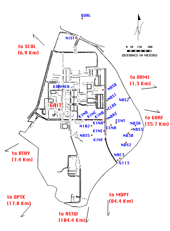
to 108 km. Figure 1 is a sketch of the general layout of the FGCS test network.
Many closely spaced stations are located within the grounds of the National
Institute of Standards and Technology in Gaithersburg, Maryland (
Figure 2).
Figure 1. FGCS test network located in the vicinity of Washington, D.C.
Figure 2. Portion of the FGCS test network near Gaithersburg, Maryland.
The WILD GPS-System 200, as configured for the test, independently tracks full-wavelength carrier phases on nine L1 and nine L2 fully independent satellite tracking channels. The modulation codes are coarse/acquisition (C/A) and P2. The receivers tested have been designed to switch to a code-aided squaring mode from a P2 demodulation mode in the event that AS is activated, using the unaffected C/A code to recover a high quality L2 squared signal. When AS is activated, the carrier measurements on the L2 are half-wavelength. The intent of the System 200 design is to provide this mode switching bi-directionally, to squaring mode and back again, for each individual satellite as AS is on or off. Because the activation of AS was sporadic on June 12th and the receivers could not be switched manually, it was not possible to test the receiver in its squaring mode. All results from this test are based on the default P-code recovery of L2.
The versions for the hardware, firmware and software tested in June, 1992, are the CR233 version 1.03, SR299 version 1.22, and SKI processing software version 1.04.
The WILD GPS-System 200 consists of two parts: a controller (CR233, version 1.03) and a sensor (SR299, version 1.22). The controller, in effect, is a wand-shaped terminal. A battery-backed static ram card also known as a "flashcard" is plugged into the controller for logging data. The flashcard is interchangeable with other flashcards in the same manner one uses a floppy disk, but it is also an integral part of the controller, its presence being necessary for the controller to function. Optionally, the operator may select to log data onto an internal memory module. The sensor has an antenna mounted atop a housing which contains an INTEL based microprocessor for data acquisition. The advantage of placing the antenna atop the signal recovery electronics is to suppress interference and noise between the antenna and preamplifier. More information on the specifications of the System 200 hardware can be found in Appendix 1.
As of April, 1993, the following improvements are featured in the firmware and software (CR233 version 1.10, SR200 version 1.43, and SKI version 1.06):
All data collected with the System 200 receiver were processed with the predicted broadcast satellite orbital coordinates. Data collected simultaneously with one or more other receivers are processed to determine relative positions (dX,dY,dZ) between occupied station points.
Various observational modes were tested that employ one or more stationary receivers, and one or more mobile or roving receivers. These modes included conventional static, rapid static, reoccupation, stop-and-go, and kinematic. Following is a brief description of each mode of observing.
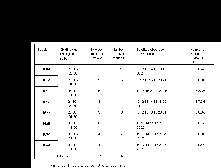
Conventional static mode generally refers to the simultaneous collection of data at two or more stations for at least an hour. Rapid static observations are similar but of much shorter duration, often only a few minutes. One or more reference tracking stations may be occupied continuously, while one or more mobile receivers move from mark to mark in the general area. No phase tracking is necessary in traversing from one location to another. Reoccupation observations (also known as pseudo-kinematic) are similar to rapid static observing except the mobile receivers will reobserve at a site an hour or more later to take advantage of the changing satellite geometry. Each mobile observation is similar in duration to a rapid static observation. Table 1 summarizes the stations occupied and the observations attempted and achieved, for both reference trackers and rovers.
Table 1. Observations attempted and achieved.

Kinematic refers to the determination of the trajectory of some moving object. One or more "roving" receivers are operated simultaneously with one or more continuous trackers. After initializing the system by resolving integer ambiguities on fixed baselines, the rovers can move along any path with the restriction that phase lock on the satellites be maintained. By maintaining phase lock the ambiguities remain constant for the entire trajectory. More elaborate scenarios are possible where receivers periodically revisit points to ensure that either continuity in phase exists or is reestablished. Stop-and-Go is an application of the kinematic method. Processed solutions are not generated every epoch along a trajectory, however, but rather only at discrete points where the roving receiver stops.
Data were collected for each of the observing modes and processed with the software SKI (static-kinematic). Since it was impractical to establish a method for evaluating positions for each individual epoch along a kinematic trajectory, kinematic trajectories were not evaluated. Only a single receiver was used as a mobile receiver in the rapid static, reoccupation, kinematic, and stop-and-go tests. All modes were successfully tested as planned. Broadcast ephemerides were used to forecast satellite positions for the scheduling of observing sessions. The observation windows were modified, however, because of a malfunctioning satellite and because the receiver had no option for overriding the transmitted health status of a satellite. Data were acquired independently for each mode tested. There were two exceptions: (1) the reoccupation mode consisted of combining the data from two rapid static sessions for sessions 160A and 161A and (2) receivers used for conventional static testing were also used as the reference trackers for other tests.
Table 2 summarizes for each session the approximate starting and ending time in UTC (Coordinated Universal Time), number of stations occupied, the PRN (pseudorandom noise) code for the satellites tracked, number of satellites at beginning and end of each session, and maximum and minimum number of satellites observed during each session.
Table 2. Observation summary, WILD GPS-System 200 FGCS test survey.

The status of the GPS satellite constellation, based on information available from the NAVSTAR GPS Information Center Bulletin Board on June 5, 1992, is summarized in Table 3. The accuracy for the predicted (broadcast) satellite orbital coordinate data used in the baseline solutions was estimated to be about 1 mm/km (1 ppm) at the 1 sigma level.
Table 3. Status of GPS satellite constellation on June 5, 1992
Partial processing had been completed by Leica at noon on Friday, June 12. This processing included the conversion of all data (except kinematic data) to Receiver INdependent EXchange (RINEX) version 2 format, and the processing of n-1 independent radial vectors. A full set of n*(n-1)/2 vectors and adjusted results were provided after the test. Preliminary results were provided for analysis and presentation at a public meeting held on Friday afternoon, June 12, 1992.
Leica's SKI software, version 1.04, was used to generate vector results. Compatible output files were generated by SKI for input to "GEOLAB" (GEOLAB, 1990), a 3-dimensional least squares adjustment program.
SKI processes data from multiple baselines using software chains in a linked architecture. This chained organization makes it possible to handle, as transparently as possible, diverse data streams, whether kinematic data is processed or conventional static data. Filenames and file structures are invisible to the user, making data management easy. The use of Microsoft WINDOWS with SKI application programs makes stepping through the processing steps via pulldown menus feel friendly. SKI runs under Microsoft Windows 3.0 or 3.1.
Two commonly available output file formats, compatible with public domain adjustment software developed and used by the National Geodetic Survey (NGS) for the inclusion of GPS data into the National Geodetic Reference System (NGRS) database, are the GFILE and BFILE (White and Love, 1991; FGCC, 1991). The GFILE, a file containing solved vectors for a GPS project, was not supported by SKI software. An independent piece of software had been invoked to reformat SKI output files into the standard GFILE format. The BFILE, a compendium of site-specific data for a GPS project, was constructed manually from observer log sheets. Code support within SKI for NGS file formats may be available in the future.
RINEX version 2 allows the processing of mixed receiver types. As the number of receivers on the market increases, the number of people co-observing with different receiver types is also increasing. Data in RINEX version 2 format were provided by Leica. Though an option to SKI is available to import RINEX version 2 data from mixed receivers, this was not tested.
SKI processing is automatic after setting some processing parameters, session sites, and reference stations. For the test the processing parameters were set to the following values, unless otherwise indicated:
Cut-off angle (degrees) : 15
Tropospheric model : Hopfield
Ionospheric model
: Standard
Ephemeris
: Broadcast
Data used : Use
Code and Phase
Frequency : L1 + L2
Limit to
resolve ambiguities (km) : 20
Kinematic chain computation rate
(epoch) : 1
a priori rms (mm) : 31
The SKI software uses standard weather data with either the Hopfield or Saastamoinen model, to compensate for the effect of tropospheric propagation delays due to the troposphere. Surface weather measurements for temperature, humidity, and atmospheric pressure were not used in the solutions.
Independent data from one or both frequencies can be used in generating a vector solution. A distance limit determines if an attempt is made to resolve integer ambiguities using the Fast Ambiguity Resolution Approach (FARA). In brief, FARA searches a volume to determine integer ambiguities, imposing statistical tests and compatibility constraints. See Eckels (1992) for details on the FARA. If a baseline length is greater than this limit, an ionospheric-free combination solution is generated that is a float solution without fixed integers. An input field is available, germane to processing kinematic data only, that sets the solution interval, as a multiple number of recording epochs, for position solutions. Finally one must set a value for the anticipated RMS solution error. This parameter, the a priori RMS, is used in the FARA algorithm to constrain ambiguities and must be set carefully to ensure proper integer fixing and solution convergence for baseline lengths less than the distance limit. If the formal estimate of the solution's RMS error is greater than the a priori RMS then the fixed ambiguity solution is rejected and a float solution provided. For baselines less than 20 km in length the FARA algorithm had indicated it solved for all sets of integer ambiguities. The a priori RMS parameter, however, was varied from 10 to 31 mm. Guidelines are given in the SKI manual for setting the a priori RMS value.
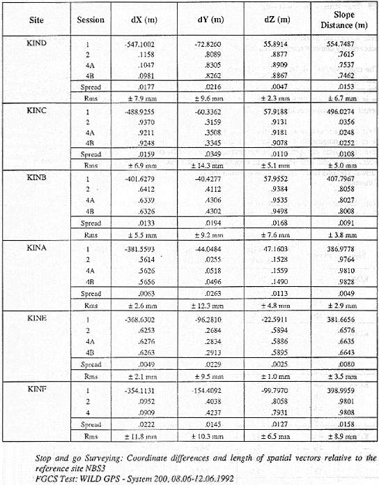
A sample of the changes in propagation delay encountered in the test is shown in Figure 3. This is a double-difference residual plot made with an independent software package, OMNI, for the longest baseline of 108 km between stations ASTW and SCOL on day 164. The magnitude of residuals for double-difference solutions using single frequency data, either L1 or L2, is approximately one cycle peak to peak. A linear-combination solution (LC) of the L1 and L2 observables provides a first order estimate for the atmospheric refraction correction. In Appendix 3 are tables containing results provided by Leica for conventional static, rabid static and stop-and-go solutions.
Figure 3. Double difference residuals for 108 km baseline using the OMNI software.

The quality of the solutions are evaluated by examining repeat vectors and residuals from a minimally-constrained least-squares adjustment. First, the components of repeat vectors are compared. This is given as the minimum and maximum component difference. Secondly, the residuals of the minimally constrained adjustments are compared with FGCS geometric accuracy standards (FGCS, 1988). These standards are summarized in Table 4. Lastly, the test results are evaluated with respect to the expected baseline precision as specified by the vendor. The baseline precision with SKI software for static, rapid static, reoccupation, and stop-and-go kinematic, are stated in the Leica technical specifications for the WILD GPS-System 200 receiver which can be found in Appendix 1.
Environmental factors may have influenced the test results. The results may have been affected by trees, buildings, nearby power transmission lines, and terrain at some of the FGCS test station sites. These test conditions are uniform from test to test, however, and frequently characterize GPS survey conditions. Thus, the FGCS stations and ambient conditions are useful in determining the effectiveness and capabilities of the GPS survey instruments and processing software.
Table 4. FGCS geometric accuracy standards

From a set of 24 baselines, repeated at least twice in 9 total sessions, the vector components were compared for each set (Table 5). Using all 72 observed baselines, a minimally-constrained adjustment yielded mean component (dX,dY,dZ) residuals of 0.012m, 0.022m, and 0.013m, respectively. Figure 4 graphically presents the component residuals and FGCS geometric accuracy standards.
Table 5. Variations in components of repeat baselines: conventional static observations


Figure 4. Residuals from least-squares adjustment: conventional static observations.
Rapid static observations were taken at 14 stations in 4 sessions. A summary is given in Table 6. The analysis of vector components, independent of recording duration, for all 22 repeat rapid static vectors is found in Table 7.
Table 6. Summary of rapid static observations

For the 70 rapid static vectors observed, adjustment residuals are plotted as a function of baseline length in Figure 5. All rapid static vectors are less than 7.5 km in length. Superimposed on this are the FGCS accuracy standards for orders B, A, and AA. The mean residuals of cartesian components from the adjustment are 0.004m, 0.008m, and 0.007m, respectively.
Table 7. Variations in components of repeat baselines: rapid static observations

Figure 5. Residuals from least-squares adjustment: rapid static observations.

Rapid static observations acquired approximately 3 hours apart at the same stations in sessions 160A and 161A were processed in the reoccupation mode. This resulted in 6 common baselines with lengths less than 2.5 km. The components were evaluated by comparing the residuals from the rapid static adjustment against the differences between the adjusted rapid static baseline and the reoccupation baseline solutions. A summary of these comparisons is given in Table 8. The reoccupation processing method produced slightly better results compared with the rapid static solutions.
Table 8. Comparison of baseline solutions: rapid static observations and reoccupation

Twelve stop-and-go vectors were repeated at least twice, their maximum length being approximately 0.55 km. The technique requires continuous phase lock on four or more satellites. The data acquisition interval is usually short, in this case 30-60 seconds. Table 9 shows that the minimum and maximum differences for the results from the repeat baselines.
Table 9. Variations in components of repeat baselines: stop-and-go observations

A least-squares minimally-constrained adjustment of 31 vectors from 10 stations, yielded mean residuals for cartesian vector components (dX,dY,dZ) of 0.003m, 0.003m, and 0.003m, respectively.
Based on the analysis of observations from the FGCS test survey, the FGCS geometric relative positioning accuracy standards are compatible with the performance of the System 200 for the various observation modes is shown in Table 10. The comments qualify the conditions upon which the classifications are based. To achieve orders A and AA, it is assumed that SKI software is capable of producing results from fixed orbital coordinate data solutions that are limited only by the accuracy of the orbit coordinate data.
Overall, the results from the predicted ephemeris solutions indicate that the WILD GPS-System 200 survey system will produce accurate results that meet or exceed the vendor's specifications. (See Appendix 2).
In conclusion, analysis of the results from the FGCS test survey conducted in June 1992 on the WILD GPS-System 200 surveying system, collected with four or more satellites in an acceptable geometric configuration, processed with double-difference software using orbital coordinate data accurate to 2 mm/km (2 ppm) or better, will yield accuracies that should meet requirements for most geodetic surveying needs.
Table 10. FGCS accuracy standards achieved for tested survey modes

Personnel representing Leica, Inc. during the test included: Henry Ayers, Charles Lee, S. Lieber, Thomas Kerr, S. Meyer, and Lloyd Penland, M. Schubernigg, and J. Schwarz.
Personnel representing the FGCS Instrument working group included: R. Anderson (test coordinator), Mark Bryant, Barbara Littell, J. Chase, D. Crockett, A. Dragoo, J. Ferguson, Janet Mean, C. Fronczek, D. Hoar, B. Leonard, D. Schultz, J Pikulsky, C. Henkel, L. Hall, D. Hoar, and L. Hothem.
We would also like to thank the following for supporting FGCS activities: Melvyn Grunthal, William Strange, and Charles Challstrom (NGS).
Eckels, R., 1992: Leica Introduces New Rapid Static; Leica Heerbrugg, Switzerland, 8 pp.
Federal Geodetic Control Committee, 1984: Standards and specifications for geodetic control networks. September 1984, reprinted February 1991, 29 pp. National Geodetic Survey Information Branch, NOAA, Rockville, MD 20852.
Federal Geodetic Control Committee, 1989: Geometric geodetic accuracy standards and specifications for GPS relative positioning surveys. Version 5.0, May 1988, reprinted with corrections August 1, 1989, 40 pp. National Geodetic Survey Information Branch, NOAA, Rockville, MD 20852.
Federal Geodetic Control Committee, 1991: Input formats and specifications of the National Geodetic Survey Data Base, Volume I. Horizontal Control Data (includes GPS). Reprinted June 1991, 250 pp. National Geodetic Survey Information Branch, NOAA, Rockville, MD 20852.
GEOsurv Inc., 1990: "GeoLab" Manual, The Baxter Centre, Ottawa, Ontario, Canada.
Hothem, L.D., and Fronczek, C.J., 1983: Report on test and demonstration of "MACROMETER ™" model V-1000 interferometric surveyor. FGCC Report IS-83-1, Federal Geodetic Control Committee. National Geodetic Information Branch, NOAA, Rockville, MD 20852.
Hothem, L.D., 1990: Test and demonstration of GPS Satellite Survey Systems. FGCC Report IS-90-1, Federal Geodetic Control Committee. National Geodetic Information Branch, NOAA, Rockville, MD 20852.
Milbert, Dennis G. and Kass, William, 1985: ADJUST: The horizontal observation adjustment program, NOAA Technical Memorandum NOS/NGS-47.
White, Madeline B. and Love, John D., 1991: Submitting GPS projects to the National Geodetic Survey: How and what?, Technical Papers of the GIS/LIS ACSM/ASPRS 1991 Fall Convention of the ACSM/ASPRS, Atlanta, GA, 75-83.
To view the image files for the WILD GPS - System 200 pamphlet, click on the page numbers below.
To view the graph, click here (254 kb).
Satellite coverage for Monday, June 6, 1992. The plots show three windows
used. To view the plots, click here (390 kb).
Traditional static; all measured baselines relative to the reference site NBS5. To view the traditional static table, click here (327 kb).
Rapid static; Comparison of coordinates for points occupied at least twice. To view the rapid static table, click here (183 kb).
Stop-and-go Surveying; Coordinate differences and lenghs of spatial vectors relative to the reference site NBS3. To view the Stop-and-go surveying table, click here (290 kb).